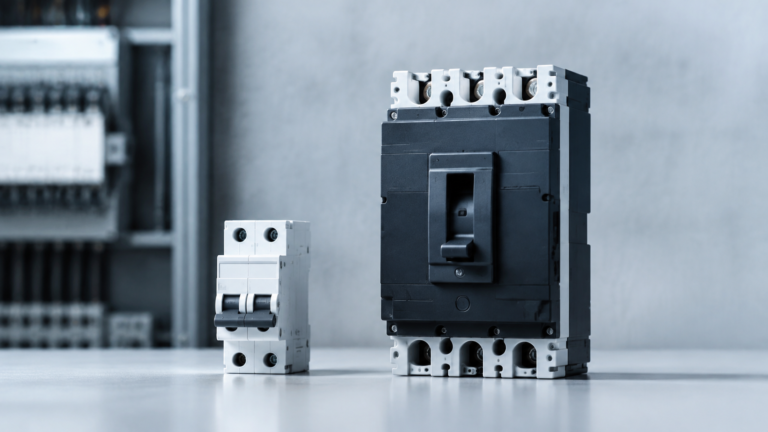


MCB vs MCCB: Key Differences and How to Choose the Right One
MCB vs MCCB explained: current range, breaking capacity, trip units, standards and applications — plus five questions that decide which breaker type your project needs.
Read More English
An AC contactor is an electrically operated switch that connects and disconnects alternating-current loads such as motors, heaters, and lighting banks. A small coil voltage does the switching work, so a low-power signal — from a pushbutton, thermostat, PLC output, or timer — can control a circuit carrying tens or hundreds of amperes. That combination of high current rating, frequent switching capability, and remote control is what makes the AC contactor one of the most widely used components in motor control panels.
This guide explains what an AC contactor is, how it works, what its main parts do, how it differs from relays and circuit breakers, and how it is wired into a typical motor circuit. If you are already past the basics and choosing a model, our AC contactor selection guide covers sizing step by step.
In a panel, an AC contactor sits between the supply and the load. When the coil is energized, the contactor closes its main contacts and the load runs; when the coil is de-energized, a return spring opens the contacts and the load stops. Because the switching action is electromagnetic rather than manual, the contactor can be operated remotely, automatically, and very frequently — thousands of operations per day in some plants.
Three properties define the job:
A contactor is a control device, not a protective device. It switches current; it does not detect faults. Short-circuit and overload protection still come from circuit breakers or fuses and an overload relay — a point that matters for correct panel design, covered later in this article.
The operating principle is electromagnetic attraction, and the sequence is the same for almost every model:
Two construction details are worth knowing because they explain behavior you will see in practice:
Contact material also matters: main contacts are typically silver-alloy, chosen for conductivity and resistance to arc erosion.
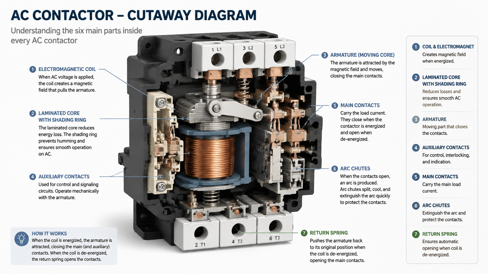
Every AC contactor is built around the same six elements:
| Part | Function |
|---|---|
| Coil and electromagnet | Converts control voltage into the magnetic force that closes the contacts |
| Armature (moving core) | The moving iron that travels when attracted, carrying the contact carrier |
| Main contacts | Switch the load current — usually 3 or 4 poles, normally open |
| Auxiliary contacts | NO and NC contacts for signaling, interlocking, and self-holding circuits |
| Arc chutes | Split and extinguish the switching arc on larger frames |
| Return spring | Opens the contacts when coil voltage is removed |
The nameplate compresses the ratings you need into a few symbols. The ones you will use most:
| Symbol | Meaning | What it tells you |
|---|---|---|
| Ie | Rated operational current | The continuous current the contactor carries at its rated duty |
| Ue | Rated operational voltage | The maximum circuit voltage for normal switching duty |
| Ui | Rated insulation voltage | The voltage the insulation system is designed for; always check it is at or above your system voltage |
| AC-1 / AC-3 | Utilization category | The load type the rating applies to — AC-1 for resistive loads, AC-3 for motor starting and running (breaking a running motor) |
| Coil voltage | Control circuit voltage | Must match your control supply; the frame does not care, but the coil does |
Utilization category deserves a second look, because it changes the current rating itself: the same physical contactor carries more current in AC-1 duty than in AC-3 duty, since switching off a running induction motor is far harder on the contacts than switching a heater. The selection guide linked above walks through the full sizing method, including how to match a contactor to motor full-load current.
As a concrete example, the LC1D 40A–65A AC contactor lists a 40–65 A current range, 690 V rated insulation voltage, AC-3 motor duty, and compliance with IEC 60947-4-1 — with the DC coil voltage, number of poles, and auxiliary contact arrangement all customizable to the panel it is going into. Exact ratings for a specific installation should always be confirmed against the product datasheet.
These three devices are often confused because all of them “switch or interrupt current,” but they answer different questions:
| AC contactor | Relay | Circuit breaker | |
|---|---|---|---|
| Primary job | Frequent remote switching of load current | Switching low-power signals | Automatic fault protection |
| Typical current range | Tens to hundreds of amperes | Usually below ~10 A | Rated by breaking capacity |
| Switching frequency | Designed for very frequent operation | Frequent | Infrequent — after a fault trip |
| Operated by | Control voltage on the coil | Control signal | Manual lever or automatic trip |
| Arc quenching | Arc chutes sized for load switching | Minimal | Heavy-duty interrupting chamber |
In short: a contactor is chosen when the question is “how do I switch this load on and off, often, under control?” — and a breaker answers “what happens if a fault occurs?” They work together in the same panel, not instead of each other. For how protection devices differ among themselves, see our comparisons of MCB vs MCCB and our explanation of breaking capacity (Icu/Ics).
Anywhere a load must be switched automatically or remotely:
Notice the pattern: in every case, a small control signal must command a much larger power current. That is the single reason contactors exist.
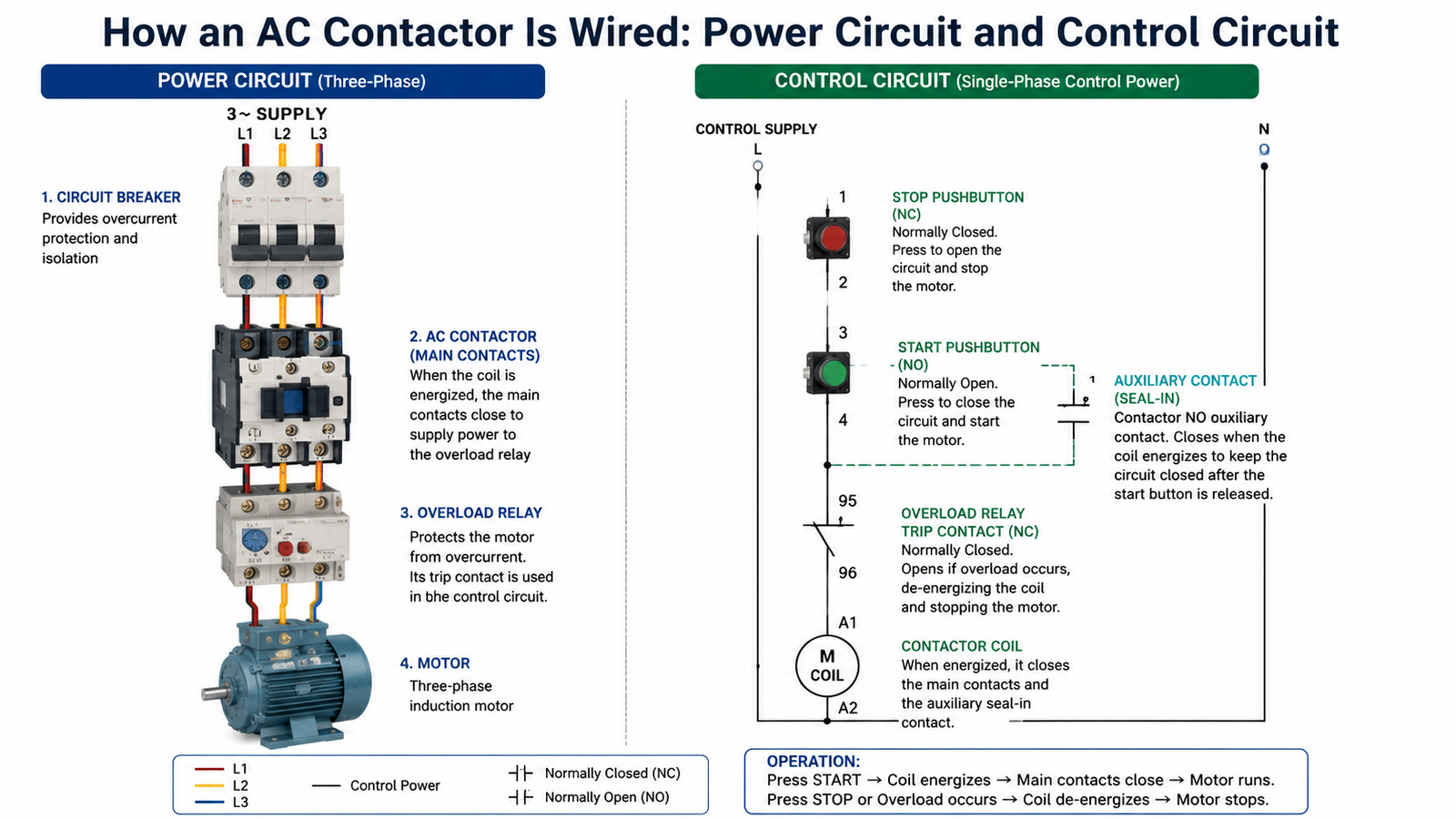
A motor circuit is really two circuits, and keeping them separate in your head makes panel wiring much easier:
When the overload relay detects sustained overcurrent, its trip contact opens the control circuit, the coil de-energizes, and the contactor drops out — the motor stops. That is a motor starter in its simplest form: contactor plus overload protection. Wire size, terminal torque, and coil voltage tolerance all follow the installation rules in the product manual.
Contactors have two different lifetimes, and the difference matters when you plan maintenance:
Basic care is correspondingly simple: keep the enclosure clean and ventilated, check that terminal connections remain tight, confirm coil voltage stays within its tolerance band, and inspect contacts for abnormal wear or discoloration during scheduled downtime. When a contactor starts chattering, running hot, or failing to close, that is a symptom with a specific cause — our AC contactor troubleshooting guide works through the common ones.
A contactor only switches. A motor starter is a contactor plus overload protection — either an attached overload relay or a dedicated protection device in the same circuit. The starter adds the “detect and trip” function the contactor lacks.
NO (normally open) contacts close when the contactor energizes; NC (normally closed) contacts open. They are used for status signaling, interlocking between contactors (for example, preventing forward and reverse contactors from closing together), and the seal-in contact in a start/stop circuit.
A quiet hum is normal for an AC coil. Loud chattering is not — it usually points to low or unstable coil voltage, a damaged shading ring, or contamination on the armature face, and it should be investigated before the contacts erode.
When a coil is switched off, its inductive kick can generate a voltage spike that stresses sensitive control devices like PLC outputs. An RC suppressor or varistor across the coil terminals absorbs that spike. It is good practice in automation-heavy panels and with electronic control devices.
Yes — use one pole for the line and one for the neutral (or wire the poles in parallel for higher current on some models, following the manufacturer’s guidance). The unused poles simply stay unwired, though frame sizing should still follow the load current.
An AC contactor is ultimately a simple idea executed with precision: a coil that turns current into magnetism, contacts that carry the load, and a spring that makes failure safe. Once you can read its nameplate, wire its control circuit, and match it to the right utilization category, specifying one becomes routine. To go from this introduction to a specific model, start with the LC1D selection guide, or browse the AC contactor and protection product range — including the LC1D 40A–65A frame with customizable coil and auxiliary options — and contact us if your panel needs a configuration that is not on the shelf.