MCB Trip Curves B, C and D Explained
What the B, C and D letters actually select, where the magnetic bands sit, and how to pick a curve from the load instead of from habit.
Leia mais
A 250 A breaker goes into a 600 × 600 enclosure because that is the size the project has always used. The device is correctly rated, the cable is correctly sized, and the panel passes its insulation test at commissioning. Eighteen months later a downstream fault trips the incomer instead of the feeder, and the enclosure door is found blackened above the outgoing way.
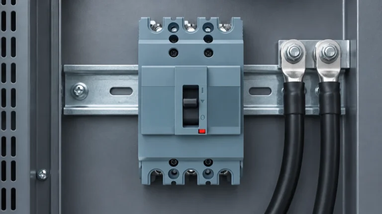
Nothing in that sequence is a breaker defect. The MCCB clearance around the device was never treated as a design input: it was whatever space was left after the busbar and the cable duct had been placed. Arc venting was not considered at all, because the breaker is a sealed moulding and it is easy to assume the arc stays inside it.
This article covers what clearance around an MCCB actually controls, where the arc gas goes and what it must not meet on the way out, and which layout decisions a panel builder can still change before the plate is drilled.
An MCCB is type-tested as a component under IEC 60947-2. The panel it sits in is verified as an assembly under IEC 61439-1 and IEC 61439-2. Those are two different verifications with two different sets of assumptions, and the gap between them is where tight layouts fail.
The component test assumes the device is mounted with whatever free space its own instructions require. The assembly verification assumes every component inside it is applied within the manufacturer’s instructions. Put a compliant breaker into an enclosure that violates those instructions and you no longer have a verified assembly — you have a collection of compliant parts in an unverified arrangement.
Three mechanisms do the damage, and they are independent:
The practical answer, before any number: the clearances that matter are the ones published for that specific device, plus the ones the assembly standard implies for the enclosure. There is no cross-brand figure. A 100 A frame and a 630 A frame in the same product family routinely have different requirements, and the requirement usually changes again with the terminal configuration.
Panel drawings tend to show one clearance dimension and ignore the rest. In practice four separate distances each control a different failure mode, and the largest of them is normally the venting one — not the wall clearance everyone draws first.
| Distance | What it actually controls | Where the value comes from | What goes wrong when it is short |
|---|---|---|---|
| Breaker body to side wall or partition | Heat rejection from the moulding and access to terminal hardware | Device instruction sheet; assembly thermal verification | Local hot spot, terminal that cannot be reached with a torque wrench |
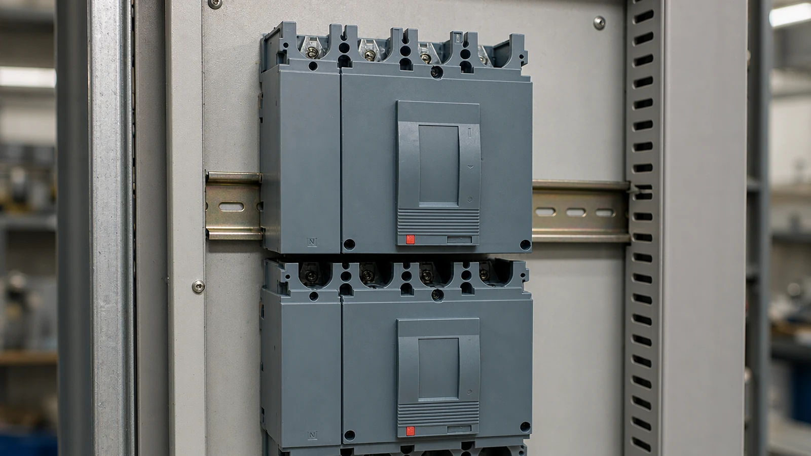
| Arc chute outlet to the nearest surface or part | Whether ionised gas can restrike to earthed metal or another phase | Device instruction sheet — the venting direction and free zone are stated there | Flashover at the exhaust after a fault, usually on the phase nearest the obstruction |
| Device to device, side by side and stacked | Mutual heating and gas impingement from the device below | Device instruction sheet plus the assembly’s temperature-rise verification | Upper device runs hot; a fault in the lower device vents into the upper one |
| Live part to cover or door | Insulation distance to accessible metal, and room for a probe or a hand | Insulation coordination per IEC 60664-1 and the assembly standard | Dielectric test failure, or an inspector’s rejection on distance to an earthed door |
Note the second row. It is the one that is almost never on a drawing, because the arc chute outlet does not look like a terminal — it looks like a vent slot in the moulding. Most MCCBs exhaust upward or forward through the front of the device, but the direction is a product characteristic, not an industry constant, and on some frames it changes with the mounting orientation. Read it off the instruction sheet for the exact catalogue number, not off a similar device already in the store.
Inside the arc chute the arc is stretched, split into a series of shorter arcs by steel plates, cooled, and deionised before it leaves. That is the whole purpose of the chute, and it works — but it works on the gas it can process, at the rate it was designed for. It does not make the exhaust harmless, and it does not make the exhaust direction optional.
What leaves the chute is a volume of very hot gas, still partly ionised, moving fast. Three consequences follow directly:
The layout rules that follow are simple to state and easy to break:
Clearance is the shortest distance through air between two conductive parts. Creepage is the distance along the surface of an insulating material between the same two parts. They fail for different reasons and they are not interchangeable: clearance is broken down by overvoltage and by ionised gas, creepage by surface contamination and moisture tracking.
IEC 60664-1 sets the framework — pollution degree, overvoltage category, material group — and the assembly standard applies it to the panel. The practical implication for a builder is that dust, condensation, and metallic swarf all reduce the effective creepage of an arrangement that measured correctly on the bench. A panel that cycles between warm and cold draws moisture onto every surface inside the enclosure, and the tracking path appears where the contamination is worst, which is usually the bottom of a vertical barrier.
Phase barriers are the part of this that gets lost. Many MCCB ranges supply insulating barriers or terminal shrouds as standard or optional accessories, and the device’s own verification assumes they are fitted. They get removed for three predictable reasons:
In each case the electrical design is unchanged and the insulation arrangement is not. That is the definition of an unverified assembly, and it is the kind of finding that stops an inspection rather than failing a test.
The ambient inside an enclosure is a layout output. It is set by the total dissipation of everything inside, divided by the surface area that can actually reject heat, adjusted for how the air moves. Clearance contributes to all three terms.
Two effects are worth designing for explicitly:
Vertical stacking. Heat rises. A column of breakers has a temperature gradient from bottom to top, and the top device in a dense column can sit several kelvin above the one at the bottom while carrying the same current. If the top device is the one with the tightest margin, the panel will trip on the top way first and the cause will look like a faulty breaker.
Grouping. Devices mounted immediately adjacent to each other share a restricted air path. The derating that applies to a single breaker in free air does not apply to a row of them in a closed box. Whether the manufacturer publishes a grouping factor or expects you to verify the assembly thermally, the direction of the correction is always the same: less space, less current.
It is worth being blunt about the consequence. A breaker selected on its nameplate rating and installed with no thermal margin does not fail safely — it nuisance-trips at normal load, and the usual response is to increase the rating, which then no longer protects the cable. Clearance, venting, and the selection steps that come before layout have to be settled together, in that order.
IEC 61439-2 defines forms of internal separation, from Form 1 (no separation) up to Form 4, with the busbars separated from functional units and terminals separated from each other. Higher forms are bought for a reason: a fault in one compartment should not propagate into the next, and maintenance on one way should not expose another.
A metal partition is the obvious way to achieve that, and it introduces two problems that are easy to miss.
Eddy currents. A steel barrier passing close to an alternating-current conductor carries induced current, heats up, and adds to the enclosure load. Barriers near high-current busbar need to be non-magnetic, or slotted to break the loop, or positioned far enough away. A barrier that solves the separation problem by creating a hot plate has moved the failure, not removed it.
Venting between compartments. A partition that blocks the arc exhaust of a device inside it turns the compartment into a pressure vessel for the duration of the fault. Internal arc testing of low-voltage assemblies is covered by IEC/TR 61641, and the arrangements that pass it generally provide a defined exhaust path rather than a sealed box. If the compartment has no relief, the gas leaves through the weakest part of the enclosure — which may be the door seal, in front of an operator.
Steel barriers also need to be earthed and bonded. An isolated metal partition standing between two live circuits is the worst of both options: it does not separate electrically and it can become live.
Every item below is cheaper to fix on the drawing than in the workshop, and most of them cannot be fixed at all once the busbar is bent.
Layout faults show up as patterns, and the pattern usually identifies the cause faster than the temperature reading does.
| What is observed | Likely layout cause | Where to look first |
|---|---|---|
| One pole or one device markedly hotter than identical neighbours at the same current | Restricted air path on that side, or a partition absorbing induced current | Spacing to the nearest surface; barrier material and slotting |
| Temperature rises steadily from bottom to top of a column | Vertical stacking with no relief at the top | Top-of-column device rating margin; enclosure vent position |
| Insulation resistance falls after a cold night or a shutdown | Condensation on contaminated creepage paths | Barrier surfaces, cable entries, enclosure sealing and drainage |
| Blackening or hardened insulation above an outgoing way | Arc gas exhaust impinging on cable or duct | Free zone at the chute outlet; cable routing across the front |
| Nuisance tripping at normal load, repeated on the same way | Enclosure ambient above the assumed value | Total dissipation, vent area, adjacent heat sources |
Only the last row is a device question at all, and even that one is usually answered by the enclosure rather than the breaker. The rest are installation conditions, which is why replacing the device rarely changes the reading.
No. Ingress protection per IEC 60529 describes resistance to dust and water. It says nothing about where hot ionised gas goes during a fault, and a well-sealed enclosure can hold the pressure in rather than let it out. Venting clearance is a separate requirement and comes from the device instructions, not from the enclosure rating.
Only if the device instructions and the assembly’s thermal verification both allow it. Physically they will fit; the question is whether the pair still carries its rated current at the resulting ambient. Where a manufacturer publishes a grouping or side-by-side factor, apply it. Where they do not, treat the arrangement as something that has to be verified, not assumed.
No. The barrier is part of the insulation arrangement the device was verified with, and removing it changes an assembly that was checked into one that was not. Change the lug or the terminal accessory instead — that is what extension terminals and spreaders exist for.
The figure is published for the specific device and depends on the exhaust direction and the frame size, which is why there is no useful general number. Take it from the instruction sheet for the exact catalogue number, apply it as a free zone rather than a minimum gap, and keep cable, duct, and labels out of it.
Because the test is done cold, clean, and without an arc. Clearance that is adequate for a dry dielectric test can be inadequate once ionised gas, condensation, or dust is present. The test verifies the arrangement as built, not the arrangement as it will operate after a fault.
The useful summary is that clearance and arc venting are specification inputs, not assembly details. They determine the enclosure size, the device spacing, the barrier scheme, and whether the assembly can still be called verified — and all four are fixed long before the first cable is landed.
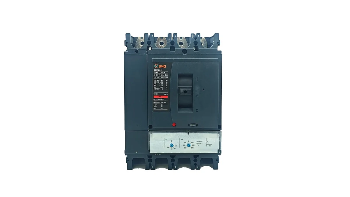
If you are laying out a panel now, the two documents that settle most of it are the instruction sheet for the exact device and the thermal verification for the enclosure. Device data per frame, including terminal and mounting information, is listed on our moulded case circuit breaker product page, and you can browse the range by frame size to compare what each size needs around it. Where the layout is still open, send the drawing with the proposed arrangement and we will confirm what the device requires before the plate is cut. Once the panel is in service, the checks in the MCCB maintenance schedule will catch a joint or a compartment that is running hotter than the layout intended.