MCCB Busbar vs Cable Connection: Torque, Lugs and Hot Joints
Busbar or cable into an MCCB terminal changes the lugs, the torque value, the bending space and the fault withstand. Here is how the joint is chosen and why it runs hot.
Leia mais
A solar installer needs a breaker on a 1000 V DC string. The wholesaler has a three-pole MCCB on the shelf, rated 36 kA at 415 V AC, and the reasoning goes: 415 V AC is a smaller number than 1000 V DC, the breaker is rated for more current than the string produces, so it will be fine. It is not fine. Put that device on a DC circuit at a voltage it was never tested for and the arc it has to interrupt does not go out the way it does on AC — and the failure mode is not a trip, it is a fire inside the enclosure.
The DC MCCB question is not about current. It is about how the arc is extinguished, and that is a property of the device, the voltage, the pole arrangement, and the circuit’s time constant together. None of those four can be substituted by a bigger current rating.
An AC arc is easy to put out because the current passes through zero twice every cycle. At the zero crossing the arc loses its energy source, the ionised path cools, and the breaker only has to prevent restrike. The arc chute helps, but the waveform does most of the work.
Direct current has no zero crossing. Once the contacts part, the current keeps flowing through the arc until something forces it to stop. The breaker has to build a counter-voltage higher than the system voltage and hold it long enough for the arc to cool. That means:
| AC circuit | DC circuit | |
|---|---|---|
| Current zero | Twice per cycle, naturally | None; must be forced |
| What extinguishes the arc | Waveform plus arc chute | Arc chute plus magnetic blowout, sustained |
| Arc duration at rated current | Short, bounded by the half-cycle | Long, bounded by the device design |
| Effect of poles | One pole per phase | Poles in series to share voltage |
| Polarity | Irrelevant | Critical, unless marked non-polarised |
| Test basis | AC test circuit | DC test circuit at a stated time constant |
| Reusing the AC figure | Valid within the AC rating | Invalid at any voltage |
The last row is the one that matters commercially. A quoted breaking capacity is a test result under a defined waveform. Change the waveform and the number no longer describes the device.
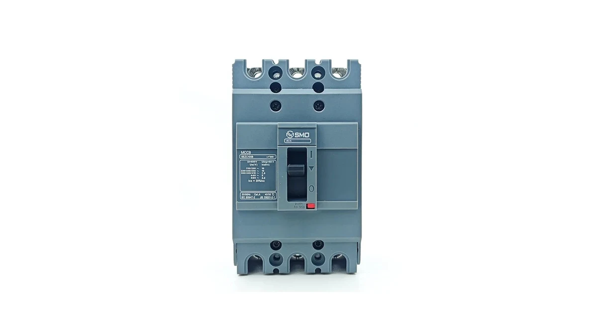
A DC rating on an MCCB is not a single number. It is a set of numbers that only make sense together:
This is why a DC MCCB datasheet looks more complicated than an AC one. It is not bureaucracy. Each line removes one way of getting the installation wrong.
A PV string is not a battery. Its behaviour at fault is different in ways that matter for breaker selection.
The array is current-limited. A shorted string produces roughly its own short-circuit current, not an unlimited fault current. That sounds easier than a battery, and for interruption it often is — but it makes protection coordination harder, because the available fault current may barely exceed the operating current.
The array behaves close to resistive. Low inductance means a short time constant, which is the easier end of the DC interruption problem. The difficulty on PV comes from voltage and from the fact that the array keeps producing while the fault is present, so the arc has a live source behind it at all times.
Reverse current is the PV-specific hazard. In an array of parallel strings, a faulted string can be fed backwards from the healthy ones. A breaker selected only for forward current will not necessarily protect against that, which is why reverse-current ratings and string protection arrangements are part of the array design, not an afterthought.
Combiner boxes get hot. A sealed enclosure in direct sun with continuous current is the worst case for any thermal-magnetic device. Whatever the ambient correction is at the switchboard, it is worse at the array. The logic in temperature and altitude derating applies with more force here, not less.
The relevant installation standard for PV systems is IEC 60364-7-712, and the array design rules sit in IEC 62548. Both push towards devices rated for the DC voltage of the string at its lowest temperature — because open-circuit voltage rises as cells get colder, and the coldest morning of the year is the sizing case, not the datasheet’s standard test condition.
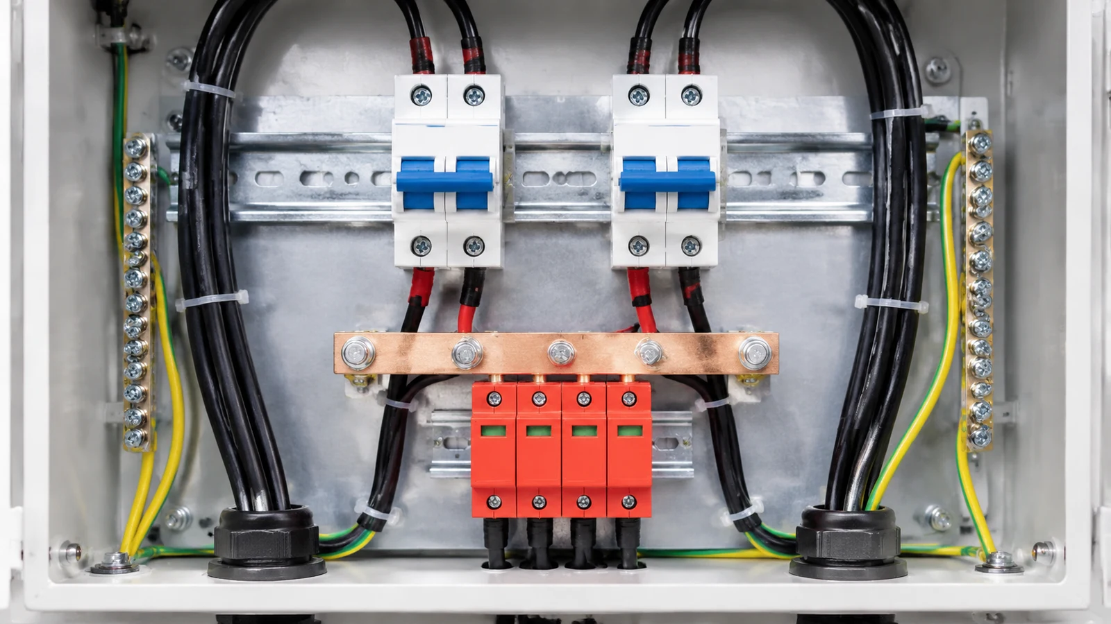
A battery bank is the opposite problem from a PV array. The available fault current is large and the source impedance is low, so the breaker sees a fast-rising current and a circuit that will sustain the arc until the device forces it down.
Three practical consequences:
Where the battery system includes a DC bus with several sources, isolation requirements usually exceed what a single breaker provides, and a labelled DC isolator is added. An MCCB is a protection and switching device; it is not automatically a means of isolation for the whole bus.
The series-pole arrangement deserves its own section because it is where most installation errors happen.
Each pole of an MCCB is built to withstand a certain voltage across open contacts. Put poles in series and the total voltage is divided between them, so the same device can be applied at a higher DC voltage — provided the manufacturer has tested and published that arrangement. The device does not do this by itself. The installer has to wire it that way, following the published diagram.
The errors that follow from getting this wrong:
Whenever a device is applied in a series arrangement, ask for the published connection diagram and keep it in the panel documentation. Inspectors ask for it, and a panel built from memory is a panel that will be rebuilt.
The purchase order is where DC projects are won or lost. Six questions separate a usable quotation from a number that looks right:
| Pergunta | Por que é importante | Acceptable answer |
|---|---|---|
| What is the DC rated operational voltage, and for which pole arrangement? | The same frame has several DC ratings; the arrangement is part of the rating | A voltage figure tied to a specific number of poles in series, with a diagram |
| What is the DC breaking capacity at that voltage, and at what time constant? | Breaking capacity without a time constant is not a testable claim | Figure plus test basis, referenced to IEC 60947-2 |
| Is the device polarised, and which terminal faces the source? | Reversed polarity moves the arc into the wrong part of the chute | Explicit marking and instruction, or a stated non-polarised design |
| What is the thermal current rating in the series arrangement? | Four poles in series is not the same thermal rating as three poles in AC service | Separate current figure per arrangement |
| Which standard and which category is the DC rating declared under? | PV and general DC duties are not interchangeable claims | Standard number, category, and the test voltage |
| Which accessories are available for DC control circuits? | AC coils and releases will not work on a DC control bus | DC-rated coil voltages and release types listed |
If a supplier cannot answer the second question — breaking capacity with its time constant — the DC rating is a marketing figure. That is not a reason to negotiate harder; it is a reason to look at a different product.
The sequence that avoids most of the failure modes:
Step three is where the AC habit does the most damage, because it is the step where a familiar current rating gets carried across from a different test condition.
Not every DC application needs a dedicated DC device. Low-voltage DC control circuits, small battery-backed systems at low voltage, and DC distribution inside equipment are often protected by devices whose DC ratings are published as part of a standard range. The test is not whether the device is marketed as a “DC breaker” but whether a DC rating exists for the voltage and arrangement in use.
Conversely, a device marketed as a DC breaker for a specific nominal voltage may not be appropriate at a higher one, even within the same product family. The rating table is the authority.
Our gama de disjuntores em caixa moldada is built on frames that carry AC ratings, with DC application available against a defined pole arrangement and test basis — if you are specifying for a PV or battery project, send us the system voltage, fault level and pole arrangement and we will confirm what the device is declared for rather than what it looks like it should do.
No. Current rating and voltage interruption are separate properties. The arc on a DC circuit does not self-extinguish at a current zero, so a device without a DC rating at that voltage has not been shown to clear the fault. Undersizing the current does not compensate.
Because the voltage across open contacts is divided between the poles in series, letting one frame reach a higher DC voltage than a single pole could clear. The arrangement must be the one the manufacturer tested and published, wired to their diagram.
Yes. A circuit with more inductance stores more energy that the arc has to absorb, so the same device interrupting the same current is a harder duty. That is why a DC breaking capacity figure is only meaningful when quoted with its test time constant.
No. An MCCB provides overcurrent protection and switching; a PV isolator provides a means of isolation for maintenance. Many installations need both, and the isolation function should not be assumed from the presence of a breaker.
The fault current. A PV array is current-limited by its own characteristics; a battery bank can deliver a very large current into a low-impedance fault. Battery applications therefore put more weight on DC breaking capacity and on the coordination study, and less on reverse-current behaviour.