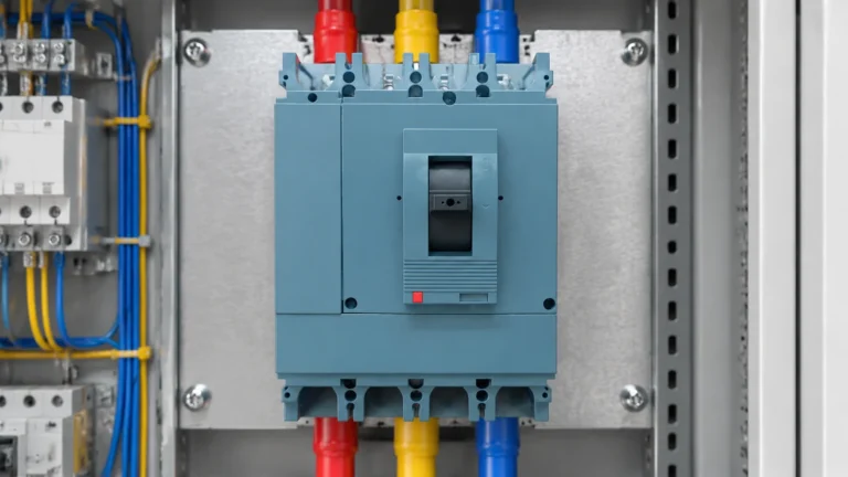
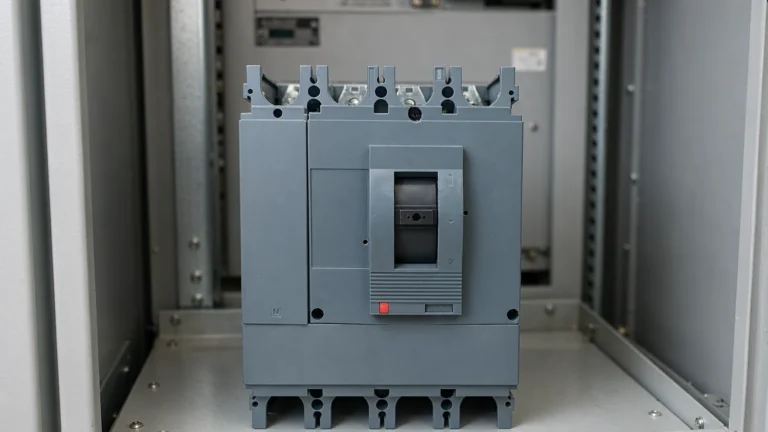
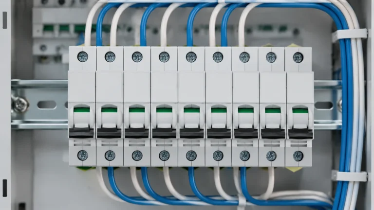
Testing an MCCB Before Installation: What Can Be Checked on Site
What a panel builder can genuinely verify on an MCCB before installation, what the readings mean, and what must be left to the manufacturer.
Leia mais
Two miniature circuit breakers, both 16 A, both from the same range, both protecting the same kind of cable. One holds in on a motor start; the other trips every time. The only visible difference is a single letter printed before the rating — B, C or D — and that letter is the whole explanation.
The curve letter sets the current at which the magnetic element operates. Everything else on the device — the thermal element, the rated current, the breaking capacity — is unchanged by it. Choosing the wrong letter does not make the breaker unsafe; it makes it either useless against inrush or slow to clear a short circuit, and both failures are blamed on the device rather than on the selection.
This article explains what each curve is for, where the magnetic thresholds sit, and how to pick a letter from the load rather than from habit.
An MCB has two protection elements in series, and they respond to different things.
O thermal element is a bimetal strip heated by the load current. It responds to overload — currents somewhat above the rating, sustained. Its behaviour is defined by the rated current and by the ambient temperature, and it is identical across B, C and D devices of the same rating.
O magnetic element is a solenoid that trips instantaneously at a high current. It responds to short circuit. Its threshold is defined as a multiple of the rated current, and that multiple is what the curve letter selects.
So the letter is not a quality grade, not a speed rating in the general sense, and not a substitute for breaking capacity. It answers one question: how much current, as a multiple of In, should cause an instantaneous trip?
For miniature circuit breakers to IEC 60898-1, the three household and light-commercial curves have defined magnetic ranges. The device must operate somewhere inside its band; the exact point within the band is a manufacturing tolerance, not a specification you can rely on.
| Curve | Magnetic trip range | Utilização típica | What it tolerates |
|---|---|---|---|
| B | 3 × In to 5 × In | Resistive loads, lighting circuits, socket outlets in domestic boards | Almost no inrush; fastest short-circuit clearance at low fault levels |
| C | 5 × In to 10 × In | General purpose: mixed loads, small motors, fluorescent lighting, most commercial distribution | Moderate inrush — the common default for a reason |
| D | 10 × In to 20 × In | Loads with very high inrush: transformers, large motors, welding equipment, some UPS and X-ray circuits | High inrush, at the cost of slower clearance for low-level faults |
Because the band is a range, two devices of the same curve and rating can behave differently at the boundary. A 16 A type C device is permitted to trip magnetically anywhere between 80 A and 160 A. If a design depends on it tripping at 90 A, that design is not supported by the standard — it is supported by one sample.
A related point: miniature circuit breakers intended for industrial use are also made to IEC 60947-2, where the curve designation and the magnetic bands are not necessarily the same as the IEC 60898-1 ones. When a device carries both markings, the band you are entitled to rely on depends on which standard it is being applied under. Read the datasheet, not the letter alone.
The useful way to think about the letter is as a filter for current that is not a fault.
Incandescent and halogen lighting draws a cold-filament surge several times its running current for a few milliseconds. Halogen and LED drivers can be worse in aggregate than a single lamp, because a board full of drivers switches on together. A type B device sees that surge as a fault and trips. This is the classic “the breaker trips when the lights come on” complaint, and the fix is usually the curve, not the rating.
Motors draw locked-rotor current — typically several times rated current — for the duration of the start, which for a direct-on-line start can be seconds. A type C device is normally adequate for small motors; a large motor, or one started against load, may need type D. Increasing the rating to stop the tripping is the wrong move, because it also raises the current the cable is protected at.
Transformers have an inrush that can reach ten to twenty times rated current for the first few cycles, decaying quickly. Control transformers and small distribution transformers are the most common reason a type D device appears in an otherwise type C board.
Capacitors and electronic power supplies produce a short, steep surge at energisation. Whether a type C holds depends on the magnitude and duration together — which is why a datasheet inrush figure with no time attached is not enough to decide.
Two constraints pull against each other, and the selection has to satisfy both.
Constraint one: the device must not trip on normal inrush. The inrush current, at the moment it peaks, must stay below the lower end of the magnetic band for long enough that the device does not respond. The lower end matters because the device is permitted to trip anywhere in its band — designing to the upper end is designing to a device you may not receive.
Constraint two: the device must still clear a fault fast enough to protect the cable. This is where the curve interacts with the installation. The thermal element protects against overload and it is set by the rating, not the curve. The magnetic element protects against short circuit, and the fault current at the end of the circuit must be high enough to operate it. On a long cable run with a high source impedance, the fault current at the far end can fall below the magnetic threshold of a type D device — and then the fault is cleared only by the thermal element, slowly, at a current the cable may not survive for that long.
That is the real cost of choosing D when C would do: not a safety failure in itself, but a reduction in the range of fault currents the device clears quickly. The check is arithmetic, and it needs three numbers:
If the far-end fault current is below the magnetic threshold, the circuit relies on thermal tripping for that fault, and the cable’s short-circuit withstand has to be checked against the time the thermal element takes. Where that check fails, the answer is a shorter run, a larger cable, or a lower curve — not a larger breaker.
These three are routinely conflated, and the confusion produces boards that are either over-specified or unprotected.
The curve sets the magnetic threshold. It has no effect on how much fault current the device can safely interrupt.
The breaking capacity — the Icn or Ics figure, in kiloamperes — sets the maximum prospective fault current the device can interrupt without damage. A type B and a type D device of the same rating can have completely different breaking capacities, because they are different products. The reasoning behind that number is covered in the breaking capacity explanation.
Selectivity is whether the upstream device stays closed when a downstream device clears a fault. It depends on the pair, not on either device alone, and for MCBs it is established by the manufacturer’s discrimination tables — the ratio of ratings, the curve combination, and sometimes the presence of a current-limiting design. Two devices of the same rating but different curves may or may not discriminate; the table is the only defensible answer.
A board that uses type D everywhere “for inrush safety” and relies on rating ratios for selectivity is a board where the discrimination has not actually been checked. The curves change the tables.
Three situations where reading the letter off the front and stopping there gives the wrong answer.
Ambient temperature moves the thermal element, not the magnetic one. A device in a hot enclosure trips on overload earlier than its rating suggests, because the bimetal starts from a higher temperature. The magnetic threshold, expressed as a multiple of In, is essentially unaffected. So a derated device in a hot board is a device whose overload protection has moved up the current scale while its short-circuit protection has not — the two no longer sit where the design assumed. The correction factors for this are the same ones that apply to any breaker in an enclosure, and the principle is set out in the derating explanation.
DC circuits. An AC magnetic element does not behave the same way on direct current, and the curve letter on an AC device tells you nothing about its DC performance. DC-rated devices are separate products with their own ratings. Reusing an AC MCB on a DC circuit because the letter looks suitable is a selection error that no amount of testing at commissioning will reveal, until the first fault.
Electronic and hybrid devices. Where the “MCB” contains electronics — an RCBO with a test circuit, a device with a communication module — the trip characteristic may be defined digitally rather than by a bimetal and a solenoid. The letter may still appear, but the tolerances and the adjustment options come from the datasheet.
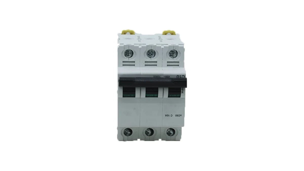
The marking is compact and it repays a few seconds of attention. A typical device shows the curve letter and the rating together — for example C 63 — with the breaking capacity elsewhere on the front, often as a small figure in a rectangle.
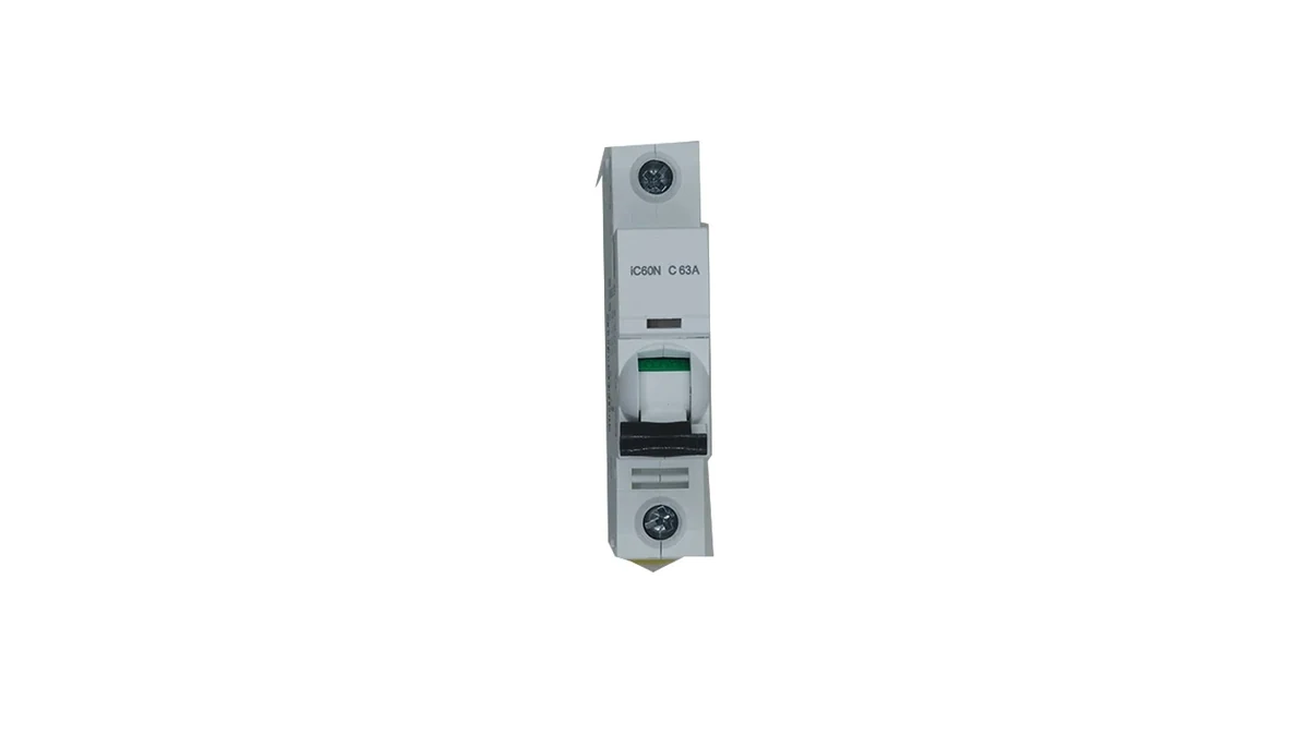
Two habits worth forming:
On a mixed board, the practical check is that every way feeding a motor or a transformer carries a C or D marking, and every way feeding a resistive or lighting circuit is not wasteful with a D. A board where all twenty ways are type C because that is what was in the store is a board where at least one way will nuisance-trip and at least one will clear too slowly.
Steps 3 to 6 are the ones that get skipped under schedule pressure, and they are the ones that decide whether the board behaves.
Sometimes, but not as a like-for-like substitution. Moving from B to C raises the magnetic threshold, which reduces the range of fault currents cleared instantaneously and changes the discrimination with the upstream device. It is a design change that needs the far-end fault current and the discrimination table checked, not a swap.
Either the inrush exceeds the lower end of the C band, or the start is long enough that the thermal element responds. The first is a curve question — a D device, or a starter that limits the inrush. The second is a rating question, and raising the rating is only acceptable if the cable is still protected at the new value.
No. D tolerates more inrush, but it also requires a higher fault current before it trips instantaneously. On a long run with a modest fault level, a D device may clear a short circuit only thermally, which is slower and harder on the cable than a C device would be.
Not necessarily. The curve and the breaking capacity are separate characteristics, and devices with different curves can come from different product families with different kA ratings. Check the figure on the device, not the letter.
Yes. Discrimination depends on the pair — the rating ratio and the curve combination both matter, and the answer comes from the manufacturer’s discrimination table for those two devices. A ratio rule of thumb that ignores the curves is not a substitute.
The curve is a small decision with an outsized effect: it sits between a board that holds in on every start and one that trips on a lighting circuit, and both are blamed on the breaker. The rule is simple — pick the rating from the cable, then pick the lowest curve that survives the inrush, then verify the fault current and the discrimination.
Our miniature circuit breaker range is listed by pole configuration and curve, and if you are building a board schedule, how to specify an MCB range covers the ordering data that has to be pinned down before quotation. For the MCCB equivalent of this skill — reading a full time-current curve rather than a single band — see how to read an MCCB time-current curve, and for where the two device families divide, MCB versus MCCB.