MCCB vs ACB: When to Step Up to an Air Circuit Breaker
Yayın tarihi: Yazar: Rachel
A panel builder once asked us to quote a 2000 A main incomer as a molded case circuit breaker. The price looked great on paper. The problem was that the same panel needed full selectivity with six downstream feeders, and the switchboard had to stay energized through a single feeder fault. No molded case breaker was going to give him that. He ended up with an air circuit breaker, and the panel worked.
That is the real question behind MCCB vs ACB. It is rarely “which one is better” — it is “at what point does the molded case stop being the right tool?” This guide answers that with the ratings that actually decide it: current range, short-time withstand (Icw), selectivity category, breaking capacity, and serviceability. It also gives you a decision framework for the 630–1600 A zone where both devices are technically available and the choice is genuinely hard.
The Short Answer: Rating Alone Does Not Decide It
If you only look at current rating, the boundary looks simple. In practice the decision splits into three zones, and the middle one is where most specification mistakes happen.
Rating zone
Default choice
Why
Up to 630 A
MCCB
Compact, cost-effective, adequate breaking capacity for most feeder duty
630–1600 A
Either — decide on selectivity, Icw and maintenance
Both technologies are available; protection requirements decide
Above 1600–2000 A
ACB
Molded case frames become impractical; ACB is the practical and usually the only choice
Notice that the middle zone is wide. A 1000 A main incomer in a factory with tight selectivity requirements is an ACB job. A 1000 A feeder to a fixed, non-critical load with no coordination study behind it is often an MCCB job, and the money saved is real. The deciding factors are not on the nameplate’s first line — they are in the protection behavior, which is where the two devices diverge.
What Actually Separates an MCCB From an ACB
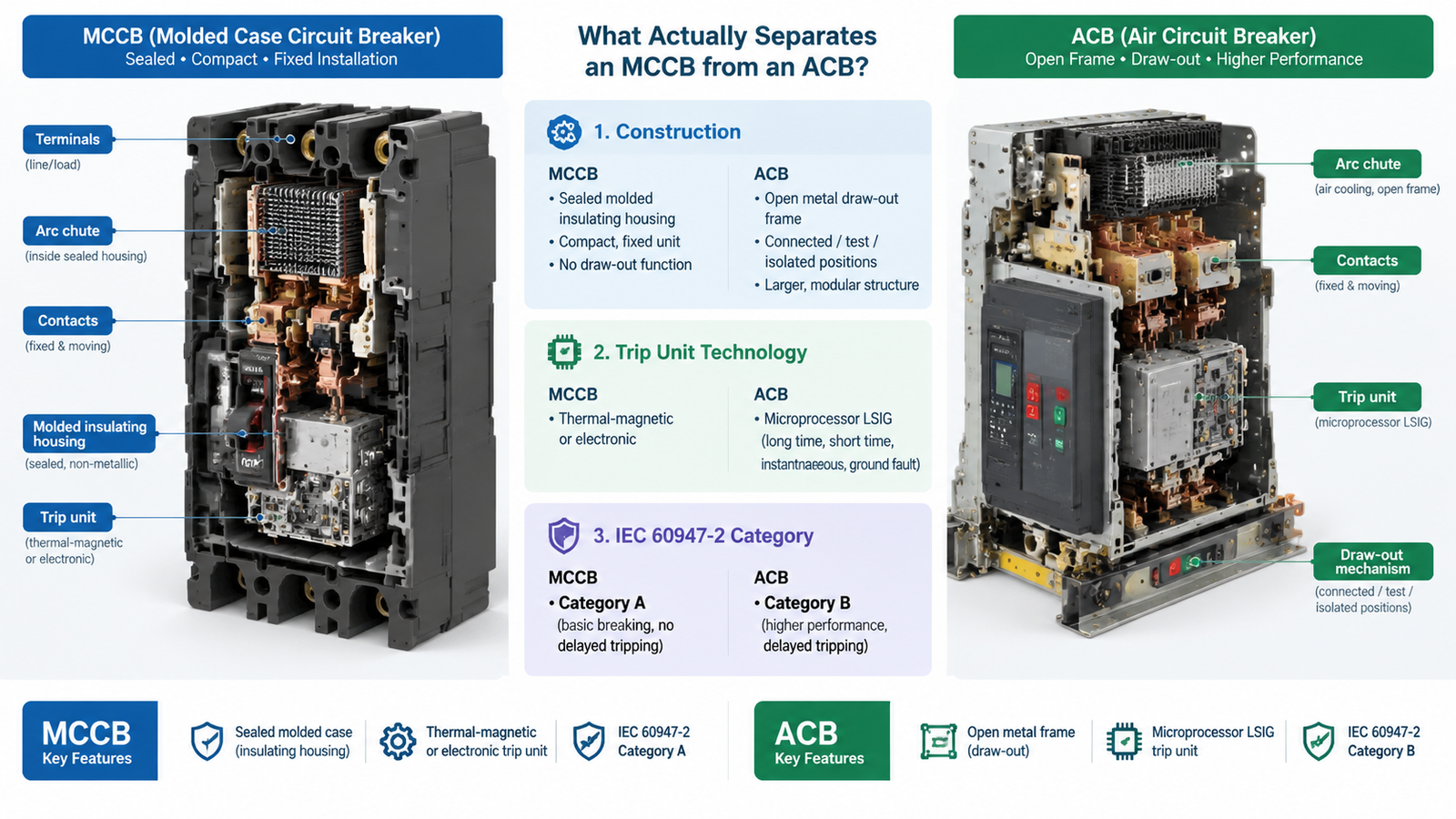
Both devices are covered by the same product standard, IEC 60947-2, for low-voltage switchgear. The differences are in construction, trip technology, and what the standard lets each one declare.
Construction: Sealed Case vs Open Draw-Out Frame
An MCCB encloses its contacts, arc chutes and operating mechanism inside a molded insulating housing. It is a sealed unit: if the trip unit fails, you replace the breaker. Most MCCBs are fixed-mounted, though plug-in and some draw-out versions exist.
An ACB uses an open metal frame. Contacts, arc chutes, the operating mechanism and the trip unit are separate modules that can be inspected, serviced and replaced. The dominant mounting form is draw-out, with three physical positions — connected, test ve isolated — which lets you rack a breaker out for maintenance without touching the busbars.
Trip Unit: What Each Device Ships With
MCCBs are commonly supplied with thermal-magnetic trip units — a bimetal element for overload and a magnetic element for short circuits — with electronic trip units as an option on larger or more adjustable frames. Thermal-magnetic units are simple and need no external supply, but their settings are fixed or only narrowly adjustable.
ACBs are almost always supplied with microprocessor-based electronic trip units providing the full LSIG function set: long-time overload, short-time with delay, instantaneous, and ground fault. Metering, event logging and communication are standard options rather than exotica. If your specification calls for adjustable ground-fault pickup or energy monitoring at the incomer, you are describing an ACB.
IEC 60947-2 Category A vs Category B
This is the formal distinction, and it is the one that matters most for selectivity.
Characteristic
Category A (typically MCCB)
Category B (typically ACB)
Intentional short-time delay
Not provided
Provided, commonly 0.05–0.5 s depending on the trip unit
Icw (short-time withstand)
Usually not declared
Declared, commonly 25–100 kA for 1 s
Selectivity method
Current limiting and energy-based discrimination
Time-graded coordination
Trip behavior under short circuit
Trips as fast as possible
Waits deliberately so downstream devices clear first
Typical duty
Feeders, sub-distribution, motor circuits
Main incomers, bus-ties, generator connections
Category A devices are described by IEC 60947-2 as not specifically intended for selectivity under short-circuit conditions. That is not a criticism — a fast, current-limiting trip is exactly what you want at the end of a radial feeder. It is simply the wrong behavior at the top of a switchboard.
Icw: The Rating That Decides Most Close Calls
Rated short-time withstand current (Icw) is the fault current a breaker can carry in the closed position for a stated duration — typically 0.05 s, 0.1 s, 0.25 s, 0.5 s or 1 s — without damage. It is the rating that makes time-graded selectivity physically possible.
Here is the mechanism. An upstream ACB waiting 0.4 s for a downstream feeder breaker to clear its fault has 0.4 s of full short-circuit current flowing through its own contacts and busbars. Without enough withstand capability, the waiting device is damaged by the very fault it is politely ignoring. That is why Category B construction uses high contact spring pressure and heavy thermal mass: the breaker must not blow its contacts apart while it waits.
MCCBs take the opposite approach. Their contacts are designed to repel electromagnetically and interrupt extremely fast, limiting let-through energy instead of withstanding it. That is excellent for protecting the downstream circuit and poor for sitting at the top of a coordination chain.
Practical consequences to check on any project:
Do not assume an MCCB has an Icw. Many do not declare one. Some larger electronic-trip frames do publish a limited Icw — read the datasheet rather than inferring it from the frame size.
Verify the Icw against the fault level in the downstream zone. If upstream selectivity requires a 0.2 s delay and the downstream prospective fault current is 40 kA, an upstream device rated 20 kA/1 s is not adequate.
Check the duration. An Icw quoted for 1 s is not the same as one quoted for 0.25 s. Compare like with like.
For the IEC minimum values that apply to Category B devices, consult the current edition of IEC 60947-2 and the manufacturer’s published data; the figures are frame-size dependent and should not be assumed from a competitor’s table.
Breaking Capacity: Where the Two Genuinely Overlap
On Icu and Ics, the two technologies are closer than most people expect. Modern MCCBs reach Icu values well above 50 kA at 415 V and, on some frames, considerably higher. Large ACBs occupy a similar band. Breaking capacity alone rarely forces you from one technology to the other in the overlap zone — it is Icw and selectivity that do.
What does differ is behavior during the fault. MCCBs current-limit aggressively, cutting let-through energy (I²t) hard. ACBs generally do not current-limit; they let the full prospective current flow until the trip unit decides to act, which is the deliberate price of time-graded selectivity. If you are protecting cable thermal withstand or sensitive downstream equipment on a fast feeder, that difference favors the MCCB.
Because the two ratings interplay, read your Icu and Ics together rather than separately — a high Icu with a low Ics ratio means a breaker that survives one big fault but may not be serviceable afterwards. Our guide to kopma kapasitesi (Icu/Ics) covers that selection detail in full.
The 630–1600 A Overlap Zone: Five Questions That Settle It
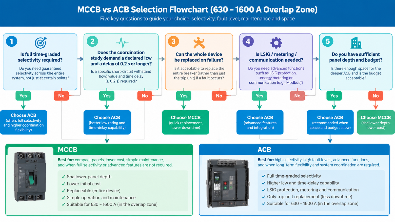
This is the zone where both devices are quoted against each other, and where a defensible decision needs more than a current rating. Work through these five questions in order.
Question
Points to MCCB
Points to ACB
Do you need full time-graded selectivity with downstream devices?
Basic discrimination is acceptable
Downstream faults must not black out the board
Is a declared Icw required by the coordination study?
No delay required, or delay is very short
Delay of 0.2 s or longer at high fault current
Can you tolerate replacing the whole device after a failure?
Yes — a spare is cheap and downtime is acceptable
No — you need to service contacts or the trip unit in place
Do you need LSIG, metering or communication at this position?
Overload and short-circuit protection only
Ground fault, power monitoring, BMS integration
How much panel depth and budget do you have?
Compact footprint, lower upfront cost
Space available, lifecycle cost drives the decision
If three or more answers fall in the right-hand column, specify an ACB. If the load is fixed, the fault study shows no need for delay, and a spare breaker sits on the shelf, an MCCB at 800 A or 1250 A is a sound engineering choice — not a compromise.
Maintenance, Downtime and Total Cost
Upfront price favors the MCCB almost every time in the overlap zone. Lifecycle cost is less one-sided.
Failure mode. A failed MCCB is replaced as a unit. A failed ACB trip unit, contact set or mechanism is replaced as a module. On a critical incomer, that difference can be hours of downtime versus a full outage window.
Isolation and testing. Draw-out construction with connected / test / isolated positions makes periodic testing and safe isolation straightforward. Fixed MCCBs need the upstream board dead, or an isolator upstream.
Spares strategy. MCCB spares are cheaper and easier to stock, but you stock whole breakers. ACB spares are modular — one trip unit spare can cover several frames.
Footprint. ACBs are substantially larger and deeper. In a space-constrained retrofit, that alone can force you back to a molded case solution, provided the protection requirements allow it.
Where Each Device Sits in a Real Switchboard
A conventional low-voltage board uses both, in a deliberate hierarchy. Understanding that hierarchy usually resolves the MCCB vs ACB question before any calculation.
Position
Typical device
Job
Main incomer / transformer secondary
ACB
Carry high continuous current, ride through downstream faults, provide LSIG and metering
Bus-tie
ACB
Selective coupling between two board sections
Generator or large feeder
ACB or large-frame MCCB
Depends on rating and delay requirement
Sub-distribution feeders
MCCB
Fast, current-limiting fault clearance
Motor circuits
MCCB or MPCB with contactor
Overload and short-circuit protection sized for inrush
Final circuits
MCB
Fixed-curve branch protection
If you are still weighing the bottom of that range, our comparison of MCB ve MCCB Karşılaştırması covers the boundary below 125 A, and the MCCB selection guide walks through sizing for feeders. For the top of the molded case range, the ISO-S7 1600 A ve SNS 800–1600 A frames are the practical ceiling of what a molded case device does well.
Specification Checklist Before You Order
Prospective short-circuit current at the installation point — from the utility or the panel designer, not estimated.
Required Icu and Ics with headroom above that fault level.
Protection functions — L, S, I, G, and whether metering or communication is specified.
Selectivity requirement — is a coordination study in the project scope, and does it demand a short-time delay?
Icw and its duration, if a delay is required.
Utilization and mounting — fixed, plug-in or draw-out; connected / test / isolated positions.
Ambient conditions — ratings are calibrated at 40 °C; hot enclosures derate the device.
Applicable standard for the destination market — IEC 60947-2 internationally; UL 489 for molded case devices and UL 1066 / ANSI C37.13 for low-voltage power circuit breakers in North America. An IEC-rated breaker is not automatically acceptable on a UL project.
Add-on functions are worth confirming at the same time. Where a residual current function is needed on a molded case frame, it is usually delivered by an add-on module rather than the breaker itself — see residual current protection explained for how those modules are specified.
Sık Sorulan Sorular
Can an MCCB replace an ACB at 1600 A?
Sometimes. If the position needs only overload and short-circuit protection, no intentional delay, and replacement-on-failure is acceptable, a 1600 A molded case breaker can be the right call. If the coordination study requires the device to ride through a downstream fault for 0.2 s or more, you need the declared Icw of an ACB.
Do MCCBs have an Icw rating?
Most do not declare one, because Category A design relies on fast interruption rather than withstand. Some larger electronic-trip frames publish a limited Icw. Never assume it — check the datasheet for the exact frame and compare the stated duration as well as the value.
Is an ACB always the correct choice for a main incomer?
No. On small boards with a single protection level and no downstream coordination requirement, a large-frame MCCB is common and correct. The ACB becomes necessary when continuous current, fault level, or selectivity demands exceed what a molded case device can declare.
What is the North American equivalent of this comparison?
Molded case circuit breakers are covered by UL 489, while low-voltage power circuit breakers — the functional equivalent of an ACB — fall under UL 1066 and ANSI C37.13. The standards test differently from IEC 60947-2, so devices are not interchangeable on paper across jurisdictions.
Can I get selectivity with two MCCBs in series?
Partial selectivity is achievable, usually through energy-based discrimination and manufacturer coordination tables that specify which frame combinations hold and up to what fault level. Full time-graded selectivity is a Category B function. If the project specification says “full selectivity,” plan for an ACB upstream.
Decide on the Protection Requirement, Not the Frame Size
The MCCB vs ACB decision is settled by what the device has to do during a fault, not by how much current it carries. Below 630 A, and in the 630–1600 A zone where no selectivity delay is required, a molded case breaker is smaller, cheaper and faster. Where the coordination study demands a short-time delay, where LSIG and metering are specified, or where the incomer must be serviced without killing the board, the air circuit breaker is the only device that genuinely does the job.
WZSMO builds molded case circuit breakers from 50 A to 1600 A with thermal-magnetic and electronic trip units, 690 V AC rating, and IEC 60947 compliance. If you are specifying the top of that range and want a second opinion on whether a molded case device will hold up in your coordination study, send us your load list, fault levels and one-line diagram and we will review it with you.
<p>Shunt trip, undervoltage release, auxiliary contacts and motor operators compared - what each MCCB accessory actually does, when to specify it, and the checklist to order the right one first time.</p>
<p>Direct-on-line, star-delta and soft starters compared on starting current, torque, mechanical stress and cost - with the four questions that decide it.</p>
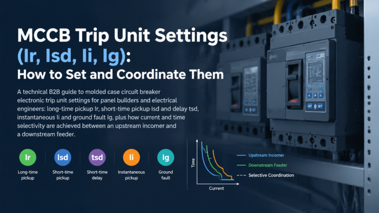
<p>What Ir, Isd, Ii and Ig mean, how to set them against the circuit rather than the frame, and how Isd and tsd deliver selective coordination between two MCCBs.</p>