MCCB vs MPCB for Motor Circuits: Which One Protects What
Published: Author: Rachel
A motor circuit is the one place in a switchboard where two protective devices sit in series and both claim to protect the same thing. The MCCB in the incomer and the MPCB in the starter bucket are not interchangeable, but they overlap enough that panels get built with one where the other belonged — and the mistake usually survives commissioning because both devices will hold the motor running on a normal day.
The difference shows up in two situations: when the motor overloads slowly, and when a downstream short circuit has to be cleared without wrecking the contactor. Which device handles each of those is decided by what the device was tested to, not by its current rating.
This article sets out the division of labour between a moulded case circuit breaker and a motor protection circuit breaker, what each is verified against under IEC 60947, where the MPCB setting routine goes wrong, why frame size quietly decides the argument above a certain rating, and how the two devices are meant to sit together in a coordinated starter. It does not quote catalogue numbers — those change; the standards and the arrangement do not.
What Each Device Is Actually Tested To
The two devices look similar, both are moulded case, both have a handle, and both are described as circuit breakers on a drawing. The difference is in the standard they are verified against and in what the verification covers.
An MCCB is a circuit breaker in the sense of IEC 60947-2. It is verified for two things: carrying its rated current indefinitely at a stated reference ambient, and breaking fault current up to its rated ultimate short-circuit capacity. Its overload element — thermal or electronic — is characterised by a conventional non-tripping current and a conventional tripping current, typically 1.05 and 1.30 times the setting, tested over a defined time. That characteristic is a cable-protection characteristic. It is not a motor characteristic.
An MPCB is a manual motor starter. Its short-circuit behaviour is also verified to IEC 60947-2, but its overload behaviour is verified as motor protection under IEC 60947-4-1, which is where the trip classes come from. A class 10 device must trip between 2 and 10 seconds at seven times its setting from cold; class 20 between 6 and 20 seconds; class 30 between 9 and 30 seconds. Those windows exist because a motor starting direct-on-line draws five to seven times its full load current for the duration of the acceleration, and the protective device must sit above that without sitting above a genuine overload.
Fixed around 13 × In, or adjustable over a narrow band
Isolation function
Yes, with a padlockable handle
Yes, with a padlockable rotary knob
Practical upper rating
Hundreds of amps and above
Roughly 100 A, occasionally 125 A
The table is the whole argument in one screen. Everything else in this article is a consequence of those rows.
The Division of Labour in a Motor Circuit
In a conventional starter, three devices sit in series and each has one job. The short-circuit protective device clears faults. The contactor switches the motor on and off, thousands of times. The overload relay protects the motor winding from sustained excess current.
An MPCB merges the first and third of those into one body. It does the short-circuit job and the overload job, and the contactor keeps the switching job. That merge is what makes the MPCB attractive: it saves a device, saves panel width, and removes the wiring between a breaker and a separate thermal relay, which is where a lot of commissioning errors live.
An MCCB does only the first job. If a motor is fed from an MCCB, the overload protection has to come from somewhere else — either a separate thermal overload relay downstream of the contactor, or an electronic trip unit on the breaker set to a motor characteristic. The second option exists but is unusual on small motors, because an electronic trip unit costs more than the motor starter it is protecting.
So the choice is not “which device is better”. It is “which job needs doing at this point in the circuit”:
Feeder or incomer protecting a group of loads — MCCB. There is no single motor to characterise, and the load is a cable.
Individual motor starter, small to medium rating — MPCB plus contactor, with the overload dial set to the motor’s full load current.
Individual motor, large rating — MCCB (or fuse) plus contactor plus a separate overload relay, because MPCBs do not reach that current.
Motor with a long acceleration time — either device, but the trip class has to be chosen deliberately rather than accepted from the default.
Where the MPCB Setting Routine Goes Wrong
An MPCB is set to the motor’s full load current, read off the nameplate. That single sentence is where most of the field errors start, because three qualifications sit behind it.
The nameplate current is at the nameplate voltage. A motor wound for 400 V and operated at 380 V draws more current for the same shaft output. Setting the dial to the 400 V figure leaves the winding marginally under-protected. On a motor with a wide voltage band stamped on the plate, the setting must follow the current at the actual supply voltage, not the highest current in the band.
Service factor and duty are not the same thing as margin. A motor rated for continuous duty at a stated ambient already accounts for its own thermal margin. Setting the overload dial above the nameplate current “to stop nuisance tripping” removes that margin from the winding and transfers the risk to the insulation. If the device trips on a healthy motor, the cause is usually the supply voltage, a mechanical overload, or an undersized starter — not a setting that needs to go up.
Ambient compensation is a band, not a promise. MPCBs are typically compensated across a stated temperature range, commonly something like −5 °C to +40 °C or +50 °C. Inside that band the trip point holds. Outside it — a starter bucket in a hot plant room, an enclosure with poor ventilation — the compensation runs out and the device behaves like an uncompensated thermal element. That is a real limitation in tropical installations and it is the reason enclosure temperature matters as much as the dial position.
Why Frame Size Quietly Decides the Argument
MPCB ranges stop where the moulded case gets too small to hold a contactor-grade mechanism and an adjustable overload element at the same time. In practice that means most ranges top out around 100 A, with a few reaching 125 A. Above that, the MPCB does not exist and the question answers itself: MCCB, contactor, overload relay.
The consequence is that a plant standard built around MPCBs will change character at exactly the rating where motors become expensive. Below the ceiling, the starter is compact and the wiring is simple. Above it, the panel grows a device and the design has to be coordinated explicitly rather than bought as a matched set.
There is a second consequence that costs more than panel space. Because MPCBs are sold as starter components, they are usually selected from a coordination table that pairs a specific MPCB with a specific contactor and a specific overload range. That table is the value — it is the manufacturer’s evidence that the combination was tested. Substituting an MPCB from one brand into a starter built around another brand’s contactor discards that evidence, even if the ratings appear to match.
Short-Circuit Coordination: Type 1 and Type 2
IEC 60947-4-1 defines two levels of coordination between a short-circuit protective device and a contactor, and the difference is not about whether the fault is cleared — it is about what is left afterwards.
Coordination
Permitted damage after a fault
Practical meaning
Type 1
Damage to the contactor and overload relay is accepted, provided they can be replaced
Fault is cleared safely; the starter is rebuilt
Type 2
No damage other than light welding of contacts, which must be separable; the device stays suitable for further use
Fault is cleared and the starter goes back into service
Type 2 is what most process plants actually want, because a starter that needs rebuilding after every downstream fault turns a nuisance trip into a maintenance job. Achieving Type 2 is not a matter of picking a bigger breaker. It requires a tested combination — a specific short-circuit device, a specific contactor, a specific overload relay, at a stated prospective fault current — and the table that proves it.
This is where an MCCB used as the motor’s short-circuit device starts to look expensive in a different currency. Its breaking capacity may be excellent, but breaking capacity is not coordination. The MCCB’s let-through energy during the fault is what stresses the contactor, and unless the pair was tested together, the claim that the contactor survives is an assumption. For a feeder that is irrelevant. For a starter it is the whole point.
For the general relationship between rated ultimate and rated service short-circuit capacity, and how those two numbers differ from a coordination claim, see breaking capacity explained.
When an MCCB Is the Right Answer for a Motor
There are four situations where an MCCB is the correct device for a motor circuit, and none of them is a compromise.
The motor is large enough that no MPCB exists. Above roughly 100 A the decision is made for you. The MCCB provides short-circuit protection with a breaking capacity that suits the fault level, the contactor switches, and a separate overload relay or an electronic trip unit handles the winding.
The circuit feeds several motors. A group starter or a busbar section feeding four motors is a feeder, not a motor circuit. One short-circuit device protects the busbar and the cable; each motor then needs its own overload protection. Feeding that arrangement through a single MPCB would leave three of the four motors unprotected against overload.
The load is not really a motor. A circuit described as a motor circuit on the drawing but carrying a mix of resistive and inductive load — a small workshop distribution way, for instance — needs a cable characteristic, not a motor characteristic. Setting a trip class 10 element to protect a cable is the wrong tool.
The application needs a short-time delay. Where selectivity against a downstream device has to be proven at a specific fault level, an electronic trip unit with an adjustable short-time stage gives a lever that a thermal-magnetic MCCB and an MPCB both lack. That lever is what makes discrimination calculable rather than asserted; the method is set out in MCCB trip unit settings.
Putting the Two Together
The arrangement that avoids the argument entirely is the one most industrial panels already use: an MCCB incomer protecting the busbar, and an MPCB in each starter bucket protecting its own motor.
In that arrangement each device is doing the job it was tested for. The incomer sees the sum of the load and protects the busbar and the incoming cable. Each MPCB sees one motor and is set to that motor’s current. Selectivity between them is not automatic — a fault in one bucket must not take out the incomer — but it is a tractable problem, because the two devices have different characteristics and a published selectivity limit can be checked against the fault level at the busbar.
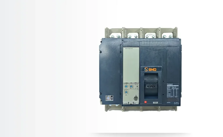
What that arrangement also gives you is a local isolator at every motor. Both an MPCB and an MCCB can be padlocked in the open position, which matters for maintenance work on a motor that is out of sight of the board. Losing that function is a common reason panels get rebuilt: somebody adds a starter without a local isolator and the maintenance procedure quietly becomes unsafe. The range of moulded case circuit breakers used for the incomer and the accessories that go with them are a separate decision from the starter design, but the two get made at the same time.
Specification Checklist
Before the devices are ordered, these fields should be filled in on the schedule. Each one changes which device is correct.
Motor full load current at the actual supply voltage — not the nameplate band maximum.
Starting method — direct-on-line, star-delta, soft starter or drive. Star-delta changes the current seen by the protective device in each of the three contactors.
Acceleration time — which decides the trip class. A high-inertia fan or a loaded conveyor may need class 20 or 30.
Prospective fault current at the starter terminals — which decides whether the coordination table even covers the installation.
Required coordination level — Type 1 or Type 2, stated explicitly rather than left to the panel builder.
Enclosure ambient — both average and maximum, since it sets whether ambient compensation still applies.
Whether a local isolator is required at the motor, and whether it must be padlockable.
Whether the circuit is a single motor or a group — because that decides between a motor characteristic and a cable characteristic.
Two of those fields — the coordination level and the enclosure ambient — are the ones most often left blank, and they are the two that produce field arguments later. The first determines what has to be replaced after a fault; the second determines whether the overload setting means anything at 45 °C.
For the panel-level view of how these starters are arranged, including the busbar and compartment questions that follow from the device choice, see motor protection in motor control panels.
Frequently Asked Questions
Can an MPCB replace an MCCB in a distribution board?
No, not as a general feeder device. An MPCB’s overload element follows a motor characteristic (trip class 10, 20 or 30) rather than a cable characteristic, and its current range stops around 100 A. Using one to protect a distribution way leaves the cable protected by the wrong curve and the rating ceiling reached very quickly.
Does a motor fed from an MCCB still need an overload relay?
Yes, unless the MCCB has an electronic trip unit configured for motor protection. A standard thermal-magnetic MCCB protects the cable against sustained overload at 1.05 to 1.30 times its setting, which is not the same claim as protecting a winding. Without a separate overload relay or a motor-configured trip unit, the winding has no dedicated protection.
Why does the MPCB trip when the motor starts, if the dial is set correctly?
Three common causes, in order of frequency: the setting follows the wrong voltage in a dual-voltage nameplate band; the acceleration time exceeds the trip class window; or the supply voltage is low, which raises current for the same shaft output. Increasing the dial hides all three and removes the winding’s margin.
Is Type 2 coordination worth the cost?
It depends on what a stopped motor costs. Type 2 means the starter returns to service after a downstream fault with nothing replaced. Type 1 means the contactor and overload relay are rebuilt. On a critical process duty the difference pays for itself on the first fault; on a spare pump that runs twice a year it may not.
Can the two device types be mixed in one panel?
Yes, and most industrial panels do exactly that: an MCCB incomer with MPCB starters downstream. The requirement is that selectivity between them is checked against the prospective fault current at the busbar, not assumed from the ratings. Mixing brands within a single starter is the arrangement to avoid, because it discards the tested coordination evidence.
An MCCB datasheet curve is one of the few documents in electrical design that rewards five minutes of careful reading with months of avoided argument. It tells you, for any fault current, how long the breaker will take to open. It also tells you whether two breakers in series will trip in the right order […]
A 250 A frame carrying 160 A looks like a mistake on a drawing. It is usually the opposite: it is what happens when someone has read the catalogue properly and separated three numbers that a datasheet prints side by side and that a lot of specifications still treat as one. The three numbers are […]
Two MCCBs sit next to each other on a quotation. Same frame, same 36 kA breaking capacity at 415 V, same pole count, same terminal layout. One is priced 30 to 40 percent above the other, and the line that explains the gap is a single word in the description: trip type. Thermal-magnetic versus electronic […]