Motor Kontrol Panelleri için Motor Koruma Kesici Kılavuzu
Yayın tarihi: Yazar: Rachel
Motor Protection Breaker and the Motor Control Panel Protection Set
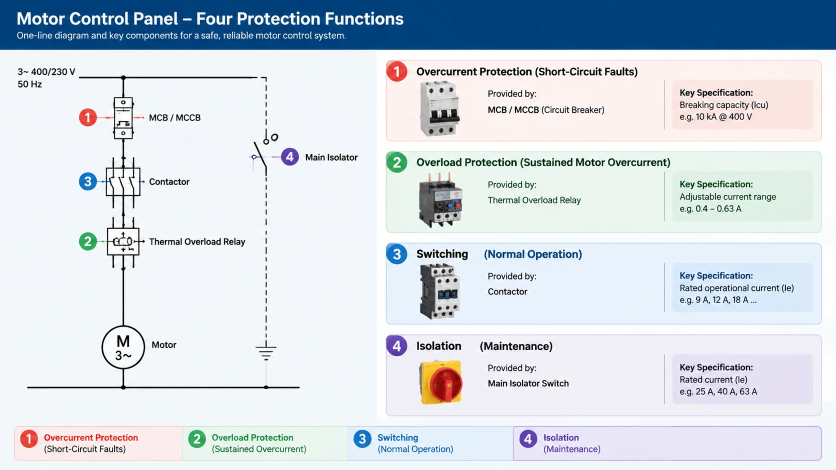
Choosing a motor protection breaker for a panel is usually treated as a single decision, but the components inside the panel are bought separately, often from different suppliers, and each one is specified independently. The overcurrent protection, the switching device, the residual current requirement and the isolation mechanism are four separate decisions that have to be consistent with each other. Getting one of them wrong does not just affect that component; it changes what the other three need to be.
This guide works through the four protection functions in a motor circuit in the order they appear in the panel, explains what each one actually does, and identifies the specification fields that buyers most often leave open. The emphasis is on purchasing, because by the time the panel is being assembled the technical choices have largely been fixed.
For guidance on the starting method itself rather than the protection components, our article on DOL versus star-delta versus soft starter covers the decision that comes before component selection.
The Four Functions a Motor Protection Breaker Setup Must Cover
A motor branch has four distinct jobs, and it helps to keep them separate:
Overcurrent protection — carries the fault current until the protective device clears it
Overload protection — protects the motor itself from sustained overcurrent, which faults do not clear
Switching — makes and breaks the motor circuit under control
Isolation — provides a safe break point for maintenance
Faults and overloads are different events, and that difference drives the component choice. A short circuit needs a device that can interrupt high current at high speed. An overload is a sustained condition that a thermal or electronic element detects over time. A single device can do both, which is what a thermal-magnetic breaker relies on, but the settings are chosen for one duty rather than the other.
Four functions, four separate decisions. Each one is bought as a separate component, and a change to any of them changes the requirements for the other three.
If a buyer specifies only a current rating, they have specified the least useful part of the device. What matters is what the device does when the motor draws its normal starting current.
Why Motor Starting Current Decides Your Motor Protection Breaker
An induction motor draws several times its rated current while starting, typically five to seven times, and that inrush lasts a few seconds. Protection has to tolerate this without tripping, while still clearing a genuine fault quickly.
This is what the time-current characteristic of an overcurrent device describes, and it is why the same current rating can behave completely differently depending on the device type and its settings. A thermal-magnetic breaker with a fixed characteristic will either tolerate a motor start or it will not, and that is decided by the manufacturer rather than by the buyer.
An electronic trip unit changes this. Adjustable long-time delay, instantaneous and short-time delay settings let the buyer set the coordination explicitly, which is what makes it the usual choice on feeders feeding motor control panels. Our article on MCCB trip unit settings covers how those settings work and what coordination means in practice.
Choosing the Overcurrent Protection for a Motor Branch
Motor branch circuits are usually protected at two levels. The upstream device protects the cable and the panel; the device local to the motor protects the motor. Both need to be specified, and they need to be coordinated with each other.
Upstream feeder protection
For a panel feeding several motors, the feeder device is selected on the cable size and the available fault current rather than on any single motor. The relevant question is whether its time-current characteristic allows the downstream motor protective device to operate first for a motor fault. If the upstream device is adjustable, that coordination is achievable. If it is fixed, it is determined for you.
Local motor protection
The device at the motor must be rated to carry the motor’s rated current continuously while tolerating the starting inrush. This is a narrower duty than panel feeder protection, and it is where a device specified only by frame size tends to go wrong: a frame selected for the fault level may not be configured to start the motor reliably.
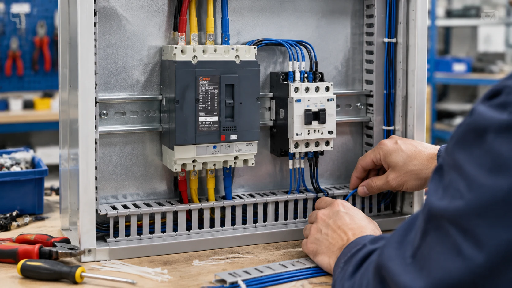
Protection and switching sit next to each other on the rail. Selecting one without reference to the other is the most common source of a mismatch found at assembly.
Contactors and What the Utilization Category Decides
The switching device in the motor circuit is a contactor, and its specification is dominated by control parameters rather than protection parameters. Rated operational current describes what the power circuit can carry. It does not describe what voltage the coil needs or how the device will be driven.
The utilization category, marked as AC-3 for motor loads, is the rating that applies to switching a squirrel cage motor under its stated conditions. Because a contactor carries different rated currents for different categories, a contactor quoted without a category cannot be compared against one that has it. AC-3 is the category to specify for standard motor duty.
Coil voltage is the field most often left open, and it is the one that causes the most returns. The coil is a separate low-voltage supply, it is usually marked on the coil rather than visible from outside the housing, and a wrong voltage makes the entire batch unusable. Our AC contactor supplier guide covers the fields that should be confirmed before a contactor order is released.
Confirming the contactor is rated for the motor, not the circuit
A common ordering error is to select a contactor by the breaker rating next to it rather than by the motor current. The breaker may be rated well above the motor current to achieve a suitable time-current characteristic, and a contactor selected to match the breaker will be oversized. Specify the contactor from the motor’s rated current and the utilization category, then check that it still fits the physical space in the panel.
Residual Current Requirements Vary by Installation
Residual current protection is a separate decision from overcurrent protection, and the required sensitivity varies substantially between installation types. A distribution board feeding commercial equipment and a final circuit serving a workshop bench do not carry the same requirement.
Two parameters govern the choice. Sensitivity is expressed as a residual current value, and typical options include 30 mA, 100 mA, 300 mA and 500 mA. The lower values are for personal protection, where a person is the protected party; the higher values are for equipment and fire protection where the concern is earth fault damage rather than shock survival.
Tripping delay is the second parameter. Instantaneous tripping suits final circuits. An adjustable delay is used where discrimination is required, so that a fault on one outgoing circuit does not trip the entire installation.
Because both the sensitivity and the delay have to match the installation type, this is a specification that should be stated explicitly rather than left at a default. Our residual current protection explainer covers the principles, and it is worth reading before specifying.
Isolation and Remote Operation
Isolation for maintenance is a separate requirement from switching. A contactor provides switching but is not an isolation device, because its contacts are not designed to be held open under load. Panel practice therefore uses a disconnect mechanism rated for isolation duty, sometimes combined with the switching function.
Where a breaker needs to be operated from a remote location rather than by hand, an operating mechanism is fitted instead of a manual handle. Electric motor-driven mechanisms receive a control signal from a PLC, relay or contact and drive a reduction gear to operate the breaker, and they typically include position feedback so the panel can report whether the breaker is open or closed. Electromagnet-operated mechanisms achieve the same result by direct electromagnet actuation of the trip rod.
Two fields are worth confirming in advance for any motor protection breaker fitted with remote operation. The control signal voltage has to match whatever is providing the signal, and the mechanism has to suit the frame current of the breaker it is fitted to. These are the two details that are usually assumed rather than specified.
A remote operation mechanism is a per-breaker decision, not a per-panel decision. The signal voltage and the frame compatibility both change with the installation.
How SMO Configures the Components in a Motor Branch
Stating our own component ranges plainly lets you check them against the points above. We supply the protection and switching elements described here; the thermal overload element for motor-specific duty is a separate device and is not part of our range.
Overcurrent protection is covered by two families. The SMO-B1 and SMO-B2 miniature circuit breakers are rated 1 A to 63 A in 1P, 2P, 3P and 4P, with 500 V insulation, 230 V / 400 V operational voltage at 50/60 Hz, 6 kA breaking capacity, and compliance to IEC 60898-1 and IEC 60947-2. For feeder and larger branch protection, the kalıplı gövdeli devre kesici serisi spans ten series from 100 A to 1600 A, with both thermal-magnetic and electronic trip units. Individual frames include the SMO-M1 100A–250A MCCB, which is certified to IEC 60947-2 and UL 489, available in 3P and 4P, and which explicitly lists motor protection among its applications.
Switching is covered by the SMO-K AC kontaktör serisi, which uses DC electromagnetic control, comes in three poles as standard, covers rated currents from 9 A to 150 A across five frame sizes, and is rated AC-3 with Icu of six to eight times rated current at 380 V. The SMO-K 40A–65A contactor is typical for mid-size motor duty.
Residual current protection is provided by the SMO-RCM residual current module, compatible with 100 A to 630 A frames, available in 30 mA, 100 mA, 300 mA and 500 mA sensitivity with instantaneous or adjustable tripping delay, rated AC 230 V / 400 V at 50/60 Hz, to IEC 60947-2 Annex B and CE.
Remote and motor-driven operation is covered by the SMO-MOP motor operator, which accepts a control signal such as DC 24 V or AC 230 V from a PLC or relay and drives a reduction gear to operate the breaker, with position feedback available through Hall sensors or encoders. An electromagnet-operated mechanism is also offered for smaller frame currents where low power consumption matters.
For a complete quotation it helps to send the motor rated current, the starting method, the required residual current sensitivity, and whether remote operation is needed. Our ODM/OEM sayfası covers private label and packaging, and enquiries can go to the iletişim sayfası. If you are still comparing suppliers rather than components, the MCCB tedarik kontrol listesi covers that side.
Questions Worth Asking a Motor Panel Component Supplier
Is the protective device configured for motor starting duty?
Ask whether the device is supplied with settings appropriate for motor inrush, and whether those settings can be changed after delivery. A fixed characteristic is a permanent constraint on the panel design.
Can the upstream and downstream devices be coordinated?
Ask for the time-current characteristics of both devices, not just their current ratings. Coordination cannot be verified from ratings alone.
Which utilization category is the contactor rated for?
Ask for AC-3 explicitly if the duty is a motor. The rated current changes between categories, so a contactor quoted without one has not been quoted against your load.
What coil voltage does this quotation assume?
And ask whether the voltage is marked on the device or only in the documentation. This is the field that most often causes a return shipment.
What residual current sensitivity and delay does this configuration provide?
Both values have to match the installation type. A module with the wrong sensitivity may be rejected at inspection even if the rest of the panel is correct.
Is the operating mechanism compatible with the breaker frame?
Ask for confirmation that the mechanism is rated for the frame current you are ordering, and what control signal voltage it expects.
Why This Matters Before the Panel Is Built
Motor control panels are assembled from components that are specified and bought separately, often over several weeks. A mismatch discovered during assembly means the panel cannot be completed, and the component that has to change is usually the one with the longest lead time.
None of the four functions described here is complicated on its own. The risk is in the interaction between them, and the interaction is exactly what a component-by-component purchase leaves unexamined.
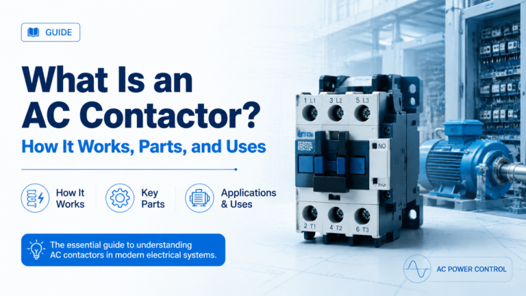
Bir AC kontaktörü, yüksek akımlı AC yükleri için kullanılan, elektrikle çalıştırılan bir anahtardır. Bobin, armatür ve kontakların nasıl çalıştığını, ayrıca parçalarını, tip plakası değerlerini, kablolama düzenini ve uygulama alanlarını öğrenin.
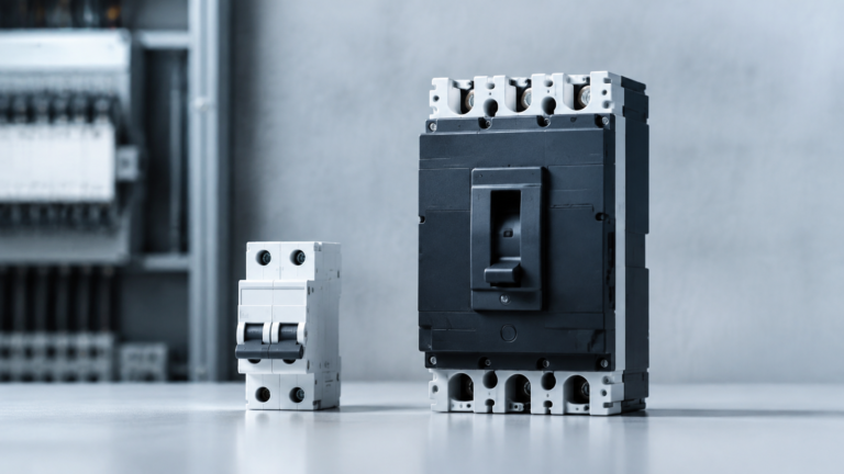
MCB ve MCCB'nin karşılaştırması: akım aralığı, kesme kapasitesi, devre kesme üniteleri, standartlar ve uygulama alanları — ayrıca projeniz için hangi kesici tipinin gerekli olduğuna karar vermenizi sağlayacak beş soru.