MCCB Derating for Temperature and Altitude: Why 250 A Is Not Always 250 A
Yayın tarihi: Yazar: Rachel
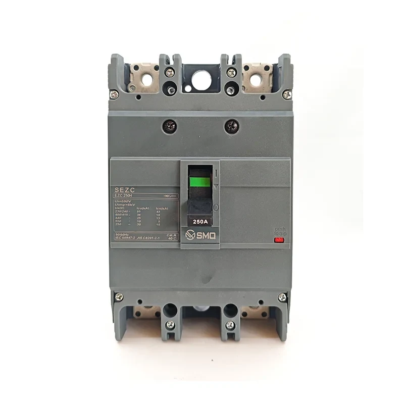
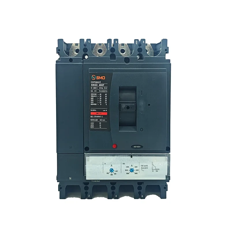
A 250 A molded case circuit breaker does not carry 250 A. It carries 250 A under a specific set of conditions that the nameplate does not spell out: a stated ambient air temperature, free air around the device, a single breaker mounted vertically, no enclosure restricting convection. Change any one of those and the number changes with it. In a real panel, all four are usually different from the reference case.
This is not a technicality. A breaker selected at its nameplate rating and installed in a sealed enclosure in a warm room will nuisance-trip on a load it is supposed to carry, and the fault will be blamed on the breaker rather than on the selection. The opposite error is worse for the cable: undersize the breaker to compensate for heat and the cable protection may no longer satisfy the coordination rule.
This guide covers the two environmental derating factors that matter most in export panel work — ambient temperature and altitude — and how they interact with enclosure design and cable protection. It deliberately avoids quoting manufacturer-specific correction factors as if they were universal. The shape of the correction is standard; the numbers come from the device documentation, and they vary between product families.
What the Rated Current Actually Assumes
IEC 60947-2 sets the framework for low-voltage circuit breakers but leaves the reference ambient temperature to the manufacturer to declare. In practice, most MCCB families are calibrated at 40 °C ambient, in free air, with the device mounted vertically as a single unit and no enclosure around it. That is the baseline the catalogue rating refers to.
Three things follow from that baseline, and each is worth stating plainly:
The 40 °C is air temperature around the breaker, not room temperature. Inside a closed enclosure the air is heated by the breaker itself, by cables, by busbars and by every other heat source in the compartment.
“Free air” means convection is unrestricted. A DIN-rail row of six breakers side by side is not free air; the devices heat each other. Manufacturers publish grouping factors for exactly this case.
The rating is a thermal equilibrium statement. It describes the current at which the bimetal reaches its trip deflection in still air at the reference temperature. Nothing about it is instantaneous.
If you are still deciding between frame sizes and trip ratings, settle that first. Derating only makes sense once you know which of the two numbers on the nameplate you are actually correcting.
Why Ambient Temperature Changes the Trip Point
A thermal-magnetic MCCB trips on overload through a bimetal element. Current passing through the bimetal heats it directly by Joule heating; the strip bends until it releases the latch. The trip point is therefore a function of total heat input, and total heat input is the sum of the current’s contribution and the ambient’s contribution.
Raise the ambient and the bimetal starts closer to its trip deflection. Less current is needed to close the remaining gap. The practical consequence: at 55 °C ambient, a breaker calibrated at 40 °C will trip below its rated current, often several percent below. This is not a defect or a tolerance issue — it is the device behaving exactly as designed.
Two details separate a careful selection from a lucky one:
Behaviour
What it means in practice
No ambient compensation on thermal-magnetic devices
The trip threshold moves with enclosure temperature. A hot afternoon shifts it; so does a cold start in winter, in the other direction.
Electronic trip units are largely ambient-compensated
The measurement is electronic, so the pickup does not drift with air temperature. The device still has a thermal limit — the current path and terminals still heat — so current derating still applies, just for a different reason.
Thermal memory
A breaker that has been carrying load is already warm. After a trip and a fast reclose, it reaches its threshold sooner than a cold device. Repeated overload trips on the same breaker get progressively easier to trigger.
The distinction in the second row is routinely missed. Electronic trip does not remove the need to derate; it removes one of the two mechanisms. Terminal temperature rise, contact heating and enclosure air temperature still constrain the continuous current. How the pickup thresholds themselves are set on an electronic unit is covered in the trip unit settings guide.
Reading a Manufacturer’s Derating Table
Every MCCB catalogue has a table of ambient correction factors, usually tucked below the ratings table. Read it as a multiplier applied to the rated current, not as an absolute current. The structure is consistent across manufacturers even where the values differ.
Ambient air around the device
Typical correction factor range
250 A frame, effective current
40 °C (reference)
1.00
250 A
45 °C
0.95 – 0.97
238 – 243 A
50 °C
0.90 – 0.94
225 – 235 A
55 °C
0.85 – 0.90
213 – 225 A
60 °C
0.80 – 0.86
200 – 215 A
65 °C
0.75 – 0.82
188 – 205 A
Those ranges are indicative of the shape of published tables, not a substitute for one. The spread between manufacturers for the same frame class is real, and it comes from differences in current path geometry, contact design and how conservatively the reference rating was declared. Use the table that ships with the device you are actually specifying.
Three reading rules that avoid most mistakes:
Apply the factor to the continuous current, not to the instantaneous setting. Magnetic pickup and short-circuit breaking capacity are not ambient-derated in the same way.
If the table stops at 60 °C, do not extrapolate. Above the published range the manufacturer is telling you the device is outside its intended application; the answer is a larger frame, not a guessed multiplier.
Grouping factors multiply. Six breakers in a row at 55 °C ambient are not corrected by one factor; the ambient factor and the grouping factor both apply, and the product is what protects the device.
Pole configuration does not change the arithmetic, but it changes which pole carries what. On a four-pole device with an unprotected neutral, the thermal load is not spread evenly across poles; the comparison is set out in the 3-pole and 4-pole MCCB comparison.
The Enclosure Is Usually the Real Limit
Here is the part that decides most real installations. The temperature that matters is the air immediately around the breaker, and inside a closed enclosure that is not the room temperature. It is the room temperature plus the temperature rise generated by everything inside the box.
That rise is a design output, not a given. It depends on the heat dissipated by the breaker, the cables, the busbars and any transformer or power supply sharing the enclosure; on the surface area of the enclosure; and on whether ventilation is provided. IEC 61439-1 governs verification of assemblies and sets limits on temperature rise for accessible surfaces and on the internal air temperature used for component selection. A panel designed and tested to that standard will have a declared internal temperature — and that declared value, not the room temperature, is what goes into the derating table.
A 250 A frame is a 250 A device only at its reference ambient, in free air, outside an enclosure.
A useful rule of thumb for early-stage layout: a closed metal enclosure with no ventilation will typically sit well above room temperature under full load, and the gap grows with packing density. If the design has not been thermally verified, the honest position is that the internal ambient is unknown, and any derating calculation built on room temperature is optimistic. Two practical options exist — verify the assembly thermally, or select with enough margin that an unverified 10–15 K error does not consume the design.
Ventilation changes the number but is not free: filters clog, IP rating drops, and in dusty or humid service conditions an unfiltered opening is often worse than the heat it removes. For enclosures rated IP65 and above, the realistic answer is usually a larger breaker rather than an opening.
Altitude: What Actually Changes Above 2,000 m
Standard low-voltage switchgear ratings assume installation at up to 2,000 m above sea level. Above that, two separate physical effects reduce capability, and they are often conflated.
Cooling. Air density falls with altitude, roughly 11 % per 1,000 m in the lower range. Lower density means lower mass flow for the same volume flow, so convective heat transfer from the breaker and cable surfaces degrades. The device runs hotter at the same current, which is a current-carrying problem.
Dielectric strength. Lower density also means lower breakdown voltage for a given gap. Clearances and creepage distances sized for sea-level service become marginal for the same rated voltage. IEC 60664-1 provides altitude correction factors for clearance, and the correction is not linear — the higher the altitude, the steeper the requirement.
Effect
Governed by
What to do
Reduced convective cooling
Manufacturer altitude derating table for current
Apply the current correction factor; treat it as cumulative with the ambient factor
Reduced dielectric withstand
IEC 60664-1 clearance correction
Verify rated voltage against the corrected clearance, or step down the operating voltage
Both together
Device documentation
Ask the manufacturer for the combined condition at your site altitude and internal ambient
Altitude derating factors are usually gentler than temperature factors over the first few hundred metres and become significant at 3,000 m and above. They are also frequently omitted in export quotations, because the enquiry rarely states site altitude. For projects in highland regions — Andean, Himalayan, East African highlands — site altitude belongs on the datasheet request along with ambient temperature.
A Worked Example
Suppose a panel builder is specifying a feeder for a 190 A continuous load. Room ambient is 35 °C. The enclosure is closed, painted steel, no ventilation, and the thermal design has not been verified. The frame under consideration is 250 A.
Estimate internal ambient. With no verification, assume the enclosure adds a meaningful rise. A working figure of 50–55 °C internal air at full load is a reasonable planning assumption for a densely packed closed box in a 35 °C room.
Apply the ambient factor. At 55 °C, a typical factor of 0.86 gives 215 A effective.
Apply grouping if relevant. If four breakers sit side by side, the grouping factor applies on top. At 0.95, the effective current falls to about 204 A.
Compare with the load. 204 A against 190 A leaves roughly 7 % margin. That is thin for a load that may run at 100 % for long periods, and thinner still if the internal ambient estimate was optimistic by 5 K.
Check the cable. The protective device must satisfy Ib ≤ In ≤ Iz and the I2 ≤ 1.45 Iz condition of IEC 60364-4-43. If the cable is sized for exactly 190 A, a breaker whose effective rating has dropped to 204 A is still acceptable on the upper bound, but the coordination margin has largely gone.
Higher frame classes buy thermal headroom, but only if the enclosure can dissipate the additional heat they generate.
The correct conclusion in that example is not to accept the 250 A frame with 7 % margin. It is either to move up a frame — which also raises the heat dissipated inside the same box, so the internal ambient rises with it — or to reduce the internal ambient by layout and segregation, or to verify the assembly thermally and work from a real number. The choice depends on which constraint is cheaper to fix.
Interaction With Breaking Capacity and Selectivity
Ambient derating changes the continuous current capability. It does not change Icu or Ics, and it does not by itself break selectivity with downstream devices. But it does move the long-time part of the trip curve, and that movement can affect coordination with a downstream breaker whose curve was compared at reference conditions.
If both devices sit in the same enclosure, both are derated similarly and the relative positions of their long-time bands stay close. If the upstream device is in a cool main switchboard and the downstream device is inside a hot local enclosure, the downstream long-time band shifts left while the upstream one does not — and a coordination study done on catalogue curves will not represent that. Where the manufacturer publishes curves at more than one ambient, the comparison should be made at the ambient the equipment will actually see.
The same logic applies to breaking capacity: a breaker whose continuous rating has been derated is still required to interrupt the prospective fault current at its terminals. That value comes from the supply, not from the load. If the prospective fault current at the installation point is not known, it needs to be established before the breaker is selected, using the method in the prospective short-circuit current calculation.
Practical Checklist for Panel Builders
State the reference ambient of the device from its own documentation — do not assume 40 °C across all families.
Establish the internal ambient of the enclosure, thermally verified if possible, conservatively estimated if not.
Apply the ambient factor, then grouping, then altitude. Multiply, do not add.
Check the effective current against the continuous load, not against the design current of the feeder alone.
Re-check cable coordination after derating: Ib ≤ In ≤ Iz and I2 ≤ 1.45 Iz.
Do not extrapolate beyond the published table. Above its range, change the frame.
Put site ambient and site altitude on the enquiry, especially for highland and tropical projects.
For electronic trip units, remember that ambient compensation removes the trip drift, not the thermal limit.
None of this is exotic engineering. It is the difference between reading a nameplate as a fact and reading it as a conditional statement — and the condition is written in the catalogue, one table below the number everyone quotes.
Sık Sorulan Sorular
Does a higher frame size solve ambient derating?
Partly. A larger frame has more thermal mass and a higher base rating, so the derated current is higher. But a larger breaker also dissipates more heat inside the same enclosure, which raises the internal ambient and works against the gain. The benefit is real but smaller than a straight ratio of nameplate ratings suggests.
Is derating needed for electronic trip MCCBs?
Yes, though for a different reason. The electronic trip unit measures current rather than responding to heat, so the pickup does not drift with ambient temperature. The current path, contacts and terminals still have a thermal limit, so the continuous current capability still falls as ambient rises. Use the manufacturer’s table for the specific device.
What ambient should I use if the enclosure is not thermally verified?
Use a conservative estimate and say so in the design record. Room temperature plus a rise for the dissipated power in the box is the starting point; without verification, a planning assumption in the 50–55 °C range for a densely packed closed enclosure in a warm room is more defensible than using room temperature. If the margin then disappears, that is the signal to verify rather than to guess again.
At what altitude does derating start?
Standard ratings assume up to 2,000 m. Above that, both current capability and dielectric withstand need correction, with the dielectric correction becoming significant at higher altitudes. Ask the manufacturer for the combined condition rather than applying a single generic factor.
Does derating affect the short-circuit rating?
Not in the same way. Icu and Ics are fault-current statements tied to the device’s interrupting capability, not to its continuous thermal equilibrium. Ambient derating addresses the long-time region. The fault level at the installation point still has to be established independently — see the Icu and Ics selection guide.
To see the frame classes available for a given derated current, start from the MCCB product range, and if the selection logic is still open, the selection guide works through the sequence from load to device.
Bir panelde yan yana iki adet MCCB bulunmaktadır. Her ikisi de 250 A'lık gövdelidir, her ikisi de 415 V'ta 36 kA nominal akıma sahiptir ve her ikisi de aynı katalog sayfasından alınmıştır. Birinin üç kutuplu, diğerinin dört kutuplu. Fiyat farkı ilginç olan kısım değil. Cevaplanması gereken soru, o dördüncü kutup herhangi bir işlev görüyor mu, […]
Çin’deki bir fabrikadan satın alma konusunda yazılmış çoğu rehber, tedarikçinin nasıl seçileceği konusuyla sınırlı kalır. Bu rehber ise o rehberlerin bittiği yerden başlıyor: Satın alma siparişi üzerinde anlaşmaya varıldı ve önümüzdeki altı hafta, sevkiyatın belirtildiği gibi mi ulaşacağı, yoksa dünyanın öbür ucundan kimsenin çözemeyeceği bir sorunla mı geleceği konusunda belirleyici olacak. […]
Eğer bir panoda halihazırda LC1D kontaktörleri kullanıyorsanız ve ikinci bir tedarikçi arıyorsanız, asıl soru bir alternatifin uyup uymayacağı değildir — çoğu fiziksel olarak uyacaktır. Asıl soru, bunun gerçekleşmesi için hangi dört unsurun eşleşmesi gerektiği ve bunların hangilerinin teknik özellik belgesinde belirtilmediğidir. Bir LC1D yedek parça kılavuzu […]