Operador motorizado para MCCB: Noções básicas sobre comutação remota
Publicado: Autor: Rachel
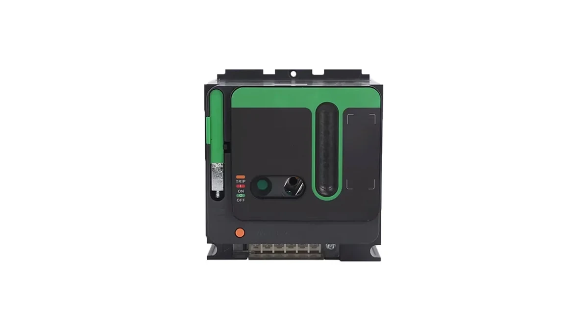
A motor operator turns a manual moulded case circuit breaker into a remotely switchable device. It bolts onto the front of the breaker, engages the same handle the electrician would pull, and charges and releases the stored-energy spring on command. Nothing about the breaker’s protection changes — the trip unit, the curves and the breaking capacity are exactly what they were.
That last point is the one that gets lost. A motor operator is an accessory, not an upgrade to the device. It adds remote operation and position feedback. It does not add switching capacity, it does not make the breaker suitable for frequent duty, and it does not turn it into a contactor. Panels that treat it as one end up with a breaker whose mechanism wears out years early and a control circuit that was never designed for the duty.
This article covers what a motor operator actually does mechanically, how the control circuit has to be arranged around it, the interlocking and feedback signals that make remote operation safe, the duty limits that decide whether it is the right choice at all, and the failure modes worth designing out before the panel leaves the workshop.
What the Accessory Actually Does
A moulded case circuit breaker stores energy in a spring and releases it to close the contacts. On a manual device, the handle does both jobs: it charges the spring and then, at the end of its travel, trips the release. A motor operator replaces the human hand with a small gear motor and a cam, and adds limit switches so the motor stops when the spring is fully charged.
The sequence for a close command is always the same:
The control circuit energises the charging motor.
The motor runs until the spring is fully charged and the charging limit switch opens.
The release is triggered, the spring discharges, and the contacts close.
The motor may re-charge immediately, ready for the next open command, depending on the design.
An open command is simpler: a release coil or a second motor action unlatches the mechanism and the opening spring does the work. On most designs the opening operation does not need the closing spring to be charged, which is why a breaker with a discharged spring can still be tripped remotely.
Two mechanical facts follow from this and both matter for panel design. First, the operator needs a defined control supply with enough current to drive a motor, not just a signal. Second, the mechanism goes through a full charge-and-release cycle on every operation, so the number of operations is a wear item, not a free action.
Because the mechanism is rigged to a specific frame, the operator is not a universal part. A unit built for one frame band — the motor operator for 100 A to 630 A frames, for instance — will not fit a breaker outside that band, and the rigging between operator and handle is set for the frame it was made for.
Where the Motor Operator Sits in the Standards
A motor operator is an accessory to a circuit breaker, and the standards treat it that way. The breaker remains a device verified to IEC 60947-2; the operator is an additional device whose combination with that breaker has to be verified by the manufacturer. The accessory does not carry a breaking capacity of its own, because it never breaks fault current — it only operates the mechanism.
Three consequences follow, and each one shows up in a specification argument sooner or later:
The combination is what is verified, not the parts. A motor operator from one brand fitted to a breaker from another is not a tested combination, whatever the mounting holes suggest.
Control circuit voltages are a separate decision from the main circuit. The operator coil may be 24 V DC while the breaker sits on a 415 V system, and the two supplies have to be arranged so that losing one does not produce an ambiguous state.
The breaker’s own ratings are unchanged. Adding an operator does not raise Icu, does not change the trip curve, and does not extend the ambient range.
Arranging the Control Circuit
The control circuit is where most of the engineering effort sits, and it is the part most often drawn as a single line with a coil on it. A workable arrangement has five elements, and leaving any of them out produces a specific failure.
Element
What it prevents
If it is missing
Local/remote selector
Two people operating the same breaker from different places
A maintenance worker is surprised by a remote close
Anti-pumping / self-hold break
Repeated close attempts while a fault is still present
The mechanism cycles until something fails
Position feedback contacts
Control logic assuming a state the breaker is not in
Interlocks release when they should hold
Separate control supply with isolation
Control faults back-feeding the main circuit
A control earth fault becomes a main-circuit fault
Emergency stop in the control circuit
Remote operation continuing during an incident
The only way to stop it is to pull the control fuse
The anti-pumping requirement deserves emphasis because it is the one that damages hardware. If a close command is held on while the breaker trips on a fault, a naive circuit will re-close immediately, trip again, and repeat. The mechanism is not designed for that cycle rate. Anti-pumping is normally achieved by wiring the close command through a contact that is broken by the breaker’s own closing, so a maintained signal produces exactly one close attempt.
Position feedback is the other element that separates a working design from a fragile one. The breaker’s auxiliary contacts report open and closed, and on some designs a “spring charged” contact as well. Control logic that infers position from the last command sent, rather than reading the contacts, will eventually be wrong — and the failure is silent until an interlock that should have held releases.
Duty Limits: What a Motor Operator Is Not For
The single most common misapplication is using a motorised breaker as a switching device for a load that operates often. A motor operator is intended for infrequent remote operations: re-energising a feeder after a planned outage, changing a source in a transfer scheme, shedding a non-essential load, isolating a section from a control room.
Three numbers bound that use, and they are all on the breaker’s data, not the operator’s:
Vida útil mecânica — the number of open/close cycles the mechanism survives without load. This is the number that governs a motorised breaker, because every remote operation consumes one.
Vida útil elétrica — the number of operations at rated current before contact erosion reaches its limit. Lower than mechanical life, and lower again at higher currents.
Operating frequency — a permissible operations-per-hour figure. Motor operators are slow by design; a charging cycle takes seconds, not milliseconds.
If a load needs to be switched several times an hour, the correct device is a contactor, with the breaker providing isolation and short-circuit protection upstream. A contactor is built for that duty and is cheap to replace; a breaker mechanism is neither. The distinction is the same one that decides how the trip unit is set, because a device used for switching sees far more operations than one used purely for protection.
There is a second duty question that is easy to miss: what the operator does when the control supply fails. Most designs hold position — the spring stays where it is and the breaker does not move. That is the safe default, but it means a control supply failure is not self-announcing. A “control healthy” signal back to the SCADA or PLC is worth the extra contact.
Interlocking and Remote Switching Schemes
Once a breaker can be operated remotely, it becomes part of a scheme, and schemes need interlocks. Three arrangements account for most of the applications.
Source transfer. Two incomers and a bus coupler, with the logic preventing two sources from being paralleled. The interlock is normally built from the breakers’ auxiliary contacts in hardware, not only in software, because a PLC output stuck high must not be able to close both. This is where position feedback stops being a convenience and becomes the safety function.
Load shedding. Non-essential feeders opened on a signal from a power management system. The breakers here operate rarely — a few times a week at most — which suits a motor operator well. The design question is the restore sequence, since re-closing several feeders at once produces an inrush that the incomer may not appreciate.
Remote isolation for maintenance. A breaker opened from a control room so that a downstream task can proceed. This is the application where a local/remote selector and a padlockable local position matter most, because the person working downstream needs to be certain the device cannot be closed remotely while they are in contact with the conductors. A motor operator does not remove the need for lock-off; it makes the lock-off procedure more important, not less.
Failure Modes Worth Designing Out
Four failures account for most field problems with motorised breakers, and all four are cheaper to prevent at design stage than to diagnose later.
The charging motor burns out. Usually caused by a limit switch that never opens, so the motor keeps driving against a fully charged spring. The motor is small and has no thermal protection of its own on many designs. A control-circuit fuse rated for the motor’s running current, not the inrush, is the standard mitigation — and it has to be sized with the inrush in mind or it will nuisance-blow on every charge.
The breaker will not close remotely but closes by hand. Almost always a control circuit problem rather than a mechanism problem: a missing permissive, a selector left in local, a blown control fuse, or a spring-charged contact that has drifted. The diagnostic is to watch the position contacts while a close command is applied, which is why bringing them out to a terminal block rather than burying them in a loom is worth the effort.
The mechanism jams after a trip. A breaker that has tripped on a fault must be reset before it can be re-closed, and on some designs the motor operator cannot perform that reset. The remote operator then has to be backed up by a manual operation, which means the panel needs to be accessible — a design constraint that a “fully remote” specification sometimes forgets.
The operator runs but nothing happens. The cam has slipped or the engagement with the breaker handle is incomplete, usually after a replacement where the operator was not re-rigged to the new breaker. This is the argument for buying the operator and the breaker as a matched pair from one source: the rigging is set at the factory and the combination is the tested one. The disjuntores em caixa moldada that accept these accessories differ in mounting and stroke between frames, so an operator matched to a 250 A frame will not fit a 630 A frame even within one range.
Lista de verificação das especificações
These fields should be settled before the operator is ordered. Each changes the part, the wiring, or both.
Breaker frame and rating the operator must fit, including whether the breaker is 3-pole or 4-pole.
Control supply voltage and type — AC or DC, and the tolerance band the site actually delivers.
Required operations per day — checked against the breaker’s mechanical life over the intended service period.
Feedback signals required — open, closed, spring charged, trip indication, and whether they go to a PLC or to indication lamps.
Whether the operator can reset after a trip — or whether a manual reset is acceptable.
Local/remote selector position and whether local operation must be padlockable.
Interlock arrangement — hardware, software, or both, and which contacts carry it.
Behaviour on control supply loss — hold position, and how that state is annunciated.
The fourth and fifth items are the ones that turn into site visits. A scheme specified with only “remote open/close” in it, and no statement of which feedback contacts are wired out, will be commissioned by whoever is on site, and the interlock will be built from whatever was available.
For the full set of accessories that mount on the same breaker — shunt trip, undervoltage release and auxiliary contacts — and how they differ from a motor operator, see MCCB accessories explained. The motor operator is often specified alongside a shunt trip and the two are sometimes confused: the shunt trip trips the breaker remotely but cannot close it, while the motor operator can do both.
Perguntas frequentes
Does a motor operator increase the breaker’s breaking capacity?
No. The operator only operates the mechanism. Breaking capacity is a property of the breaker, verified to IEC 60947-2, and it does not change when an accessory is fitted. A motor operator also never interrupts fault current itself.
Can a motorised MCCB replace a contactor for frequent switching?
No. A motor operator is intended for infrequent remote operations. Every remote close and open consumes mechanical life, and the charging cycle takes seconds. Loads that switch several times an hour need a contactor, with the breaker providing isolation and short-circuit protection.
What happens if the control supply fails while the breaker is closed?
On most designs the breaker holds its position — the mechanism does not move and the main circuit is unaffected. The breaker simply cannot be operated remotely until the supply returns, which is why a control-healthy signal is worth wiring back to the monitoring system.
Can a motor operator be added to a breaker already in service?
Usually yes, if the operator is the one specified for that breaker frame by the same manufacturer. What cannot be done safely is fitting a third-party operator to a breaker it was not designed for: the mounting may work but the stroke and the spring rigging will not be the tested combination.
Why does the breaker not re-close after tripping on a fault?
Because it has to be reset first, and on some designs the motor operator cannot perform that reset. That is a deliberate safety behaviour, not a fault. The design consequence is that a panel claiming full remote operation still needs to be accessible for a manual reset after a trip.
Um circuito de motor é o único local num quadro elétrico onde dois dispositivos de proteção estão ligados em série e ambos têm como função proteger o mesmo elemento. O MCCB na entrada de alimentação e o MPCB no compartimento do arrancador não são intercambiáveis, mas as suas funções sobrepõem-se o suficiente para que os quadros sejam construídos com um no lugar onde deveria estar o outro — […]
A curva apresentada na ficha técnica de um disjuntor MCCB é um dos poucos documentos na conceção elétrica que, em troca de cinco minutos de leitura atenta, permite evitar meses de discussões. Indica, para qualquer corrente de falha, quanto tempo o disjuntor demorará a abrir. Também indica se dois disjuntores ligados em série irão disparar na ordem correta […]
Uma estrutura de 250 A que suporta 160 A parece um erro num desenho. Normalmente é o contrário: é o que acontece quando alguém lê o catálogo corretamente e separa três valores que uma ficha técnica apresenta lado a lado e que muitas especificações ainda tratam como um só. Os três valores são […]