DC MCCB for Solar and Battery Systems: Why AC Ratings Do Not Transfer
A DC rating is not an AC rating carried over. Arc extinction, poles in series, time constant and polarity decide what a solar or battery circuit can actually use.
Leia mais
A panel builder buys a 400 A moulded case circuit breaker, bolts it to a plate, and connects it. Two years later the joint at the bottom terminals is running at 78 °C in a 35 °C room, the cable insulation has hardened, and nobody can say whether the breaker was ever the problem. In most of these cases the breaker is fine. The connection is not.
The MCCB busbar connection decision is usually made late, by whoever is building the panel, on the basis of what is in the store room. That is the wrong order. Whether a feeder leaves the breaker as a copper bar or as a cable changes the terminal hardware, the torque value, the bending space, the derating, and the fault withstand of the joint — and it changes them before the enclosure layout is fixed, not after.
This article covers what an MCCB terminal will actually accept, how busbar and cable connections differ in service, and the specific mistakes that turn a correct breaker into a hot joint.
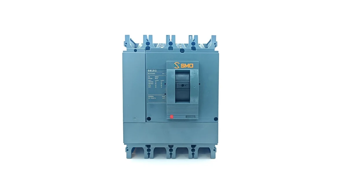
An MCCB does not have a “cable terminal” and a “busbar terminal” as separate product variants in most ranges. It has one terminal well per pole, and the hardware inside that well determines what can be clamped. The choice is therefore about three things:
The practical consequence: decide the connection method when you select the breaker, because the terminal configuration and the accessory list (extension terminals, spreaders, lug kits) follow from it. Retrofitting a busbar connection onto a breaker supplied with cable-only terminals is where most schedule slippage comes from.
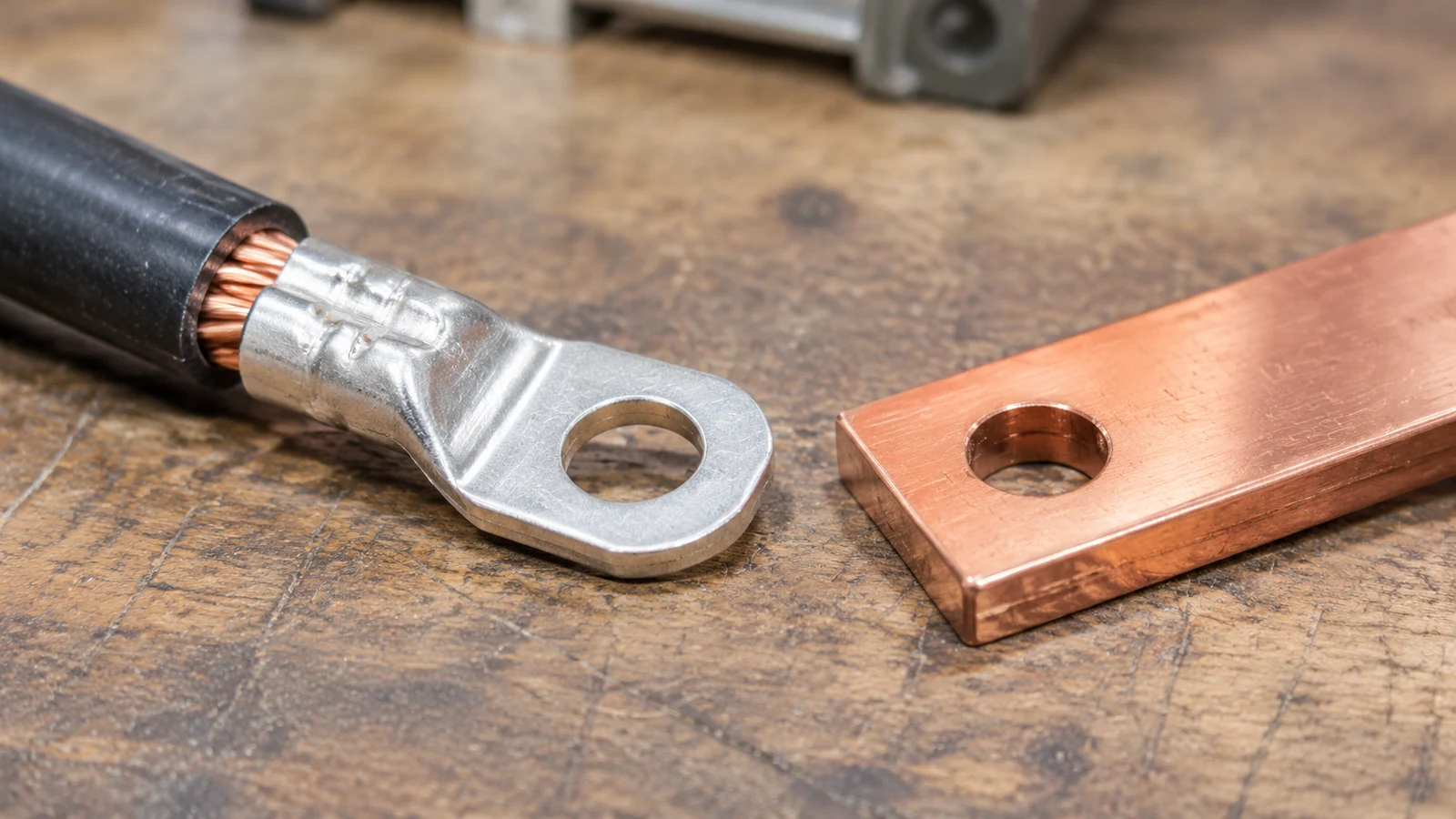
Three terminal families cover most of the market, and each has a hard limit that is easy to miss.
The conductor or lug is inserted into a rectangular well and clamped by a plate driven by one or two screws. These accept bare stranded conductor, ferrules, and compression lugs within a stated range. The limits that matter are the maximum conductor cross-section per pole and the maximum lug barrel diameter. A lug that fits the conductor may still be too wide for the well, and forcing it spreads the pressure plate so that it clamps the lug on two edges instead of on the barrel.
A threaded stud with a nut and washers. These accept ring lugs and drilled bar, and the joint quality depends almost entirely on flat contact area and correct hardware. A ring lug on a stud is a good joint when the lug face is flat and the washer stack is right. It is a poor joint when the lug is stamped with a raised seam, or when the bar is drilled with a hole that has a burr on the contact face.
Some ranges offer front terminals or plug-in bases so that a feeder can be changed without removing the breaker. These add a contact interface inside the enclosure, which is a second joint to maintain. Useful for switchgear that must be maintained live-adjacent; unnecessary cost on a fixed distribution board.
Whichever family applies, two numbers must be confirmed from the device documentation before the panel drawing is released: the conductor range per terminal, and the tightening torque. Neither should be inferred from the frame size. See why frame size and rated current are different numbers for how the frame number misleads on terminal sizing as well.
Busbar is the default for anything above roughly 250 A, and for good reasons that are rarely written down.
It pays where:
It bites where:
Bar cross-section does not by itself determine current rating. Spacing between bars, orientation (edge-on versus flat), enclosure material, paint, and adjacent heat sources all move the number, which is why a bar table copied from a catalogue without the associated conditions is worth very little. The same logic that applies to temperature and altitude derating applies to the bar: the catalogue figure assumes conditions the panel probably does not meet.
Cable is the default below roughly 250 A, and it fails for different reasons than busbar.
Conductor class matters. IEC 60228 defines flexible and stranded conductor classes. A class 5 flexible conductor in a box terminal without a ferrule will spread under clamping pressure; strands migrate, the joint loosens over thermal cycles, and resistance climbs. The fix is a ferrule or a compression lug, not more torque.
Lug selection is a two-variable problem. The barrel must match the conductor cross-section and class, and the palm must match the terminal stud or well. A lug that is correct on the cable and wrong at the palm is the most common mismatch in small panels, and it is invisible once the cover is on.
Crimp quality is not visible. A correct crimp has the right die for the lug, the conductor fully inserted to the barrel stop, and no strand cut. A crimp that looks neat but was made with the wrong die has high resistance and will show up as a warm joint months later. Mechanical lugs with a setscrew are acceptable where the manufacturer specifies them, but the setscrew bears on the conductor directly and must be re-checked after the first thermal cycle.
Insertion depth. Box terminals have a stop. Conductor inserted short of the stop clamps on fewer strands and on the insulation transition; conductor inserted past the stop, where the well allows it, can foul the terminal body. Both are torque-correct and electrically wrong.
Torque is where panel-building culture and product documentation most often diverge. A fitter who has built one range for years carries a feel for it, and that feel is calibrated to a different terminal design.
The only defensible value is the one published for that specific device and terminal, on the label, in the instruction sheet, or in the catalogue. Three points follow from that:
Use a calibrated torque wrench with the correct socket. A screwdriver handle with a torque scale is a reasonable compromise on small terminals; it is not acceptable on a 400 A bar joint. Where a terminal has two screws, tighten them in stages rather than fully tightening one and then the other.
Almost every hot joint traced back in a distribution board falls into one of six patterns. The symptom column is what a thermal scan or an infrared check actually shows.
| Failure pattern | What was done | Symptom under load | Corrective action |
|---|---|---|---|
| Lug on the wrong face | Ring lug clamped against the terminal moulding instead of the flat pad | One pole hotter than the others at low load; gap visible at the interface | Refit with the correct lug orientation and flat washer stack |
| Burred contact face | Bar drilled or punched after tinning, no deburr | Hot spot localised around the bolt, not across the pad | Face the pad flat, re-tin if required, remake the joint |
| Strand migration | Flexible conductor in a box terminal without ferrule | Gradual rise over weeks; resistance climbs with each cycle | Refit with ferrule or compression lug |
| Relaxed bolted joint | Torqued once, never re-checked; no spring washer | Warm at first inspection, hot at the next one | Re-torque to the published value, add the specified washer |
| Unsupported bar | Long bar run from terminal with no insulator | Heat at the terminal plus mechanical movement under fault | Add support close to the terminal; shorten the cantilever |
| Mixed metal without transition | Aluminium bar bolted direct to bare copper | Rising resistance at the interface over months | Use a listed transition or bimetallic interface |
Note that only one of these six is a breaker problem. The rest are connection problems, which is why replacing the device rarely fixes a hot joint.
The joint cannot be verified by looking at it. Verification is a sequence:
Temperature rise limits for terminals are set in the product standard and depend on terminal material and part; they are not a single universal number to design to. For panel work the more useful rule is comparison between identical joints under identical current.
Most connection problems are purchased, not built. A purchase order that says only “400 A MCCB, 3 pole, 50 kA” leaves the terminal configuration open, and the supplier will ship whatever the standard build is.
Four lines in the order prevent most of it:
If the panel is being designed around a specific bar size, state the bar thickness and hole pattern. A terminal that accepts the bar but not the bar’s thickness is a problem discovered at assembly, when the schedule is least able to absorb it. Our gama de disjuntores em caixa moldada lists terminal and connection data per frame, and if the drawing is still open you can send us the panel drawing and we will confirm what the terminal will accept before the order is placed.
Only if the terminal is designed for it. Stacking a lug on top of a bar at one stud changes the clamping stack height and usually exceeds the hardware the manufacturer supplied. Where a mixed connection is genuinely needed, use the manufacturer’s spreader or a dedicated adapter rather than a longer bolt.
No. Above a certain current, parallel cables become impractical and bar is the sensible answer. Below it, a correctly lugged cable is a good joint with fewer parts and easier fault-finding. The decision should follow the number of outgoing ways, the fault level, and the maintenance access, not the current alone.
Once after the first thermal cycle is the minimum, and then at each scheduled maintenance interval for bolted joints. Compression joints and crimped lugs do not need routine re-torque, but they do need thermal scanning, because a bad crimp cannot be detected by feel.
Usually not. Compare the three poles at the same current first. If one pole is hot, suspect that joint’s hardware, lug, or torque. If all poles are hot together, suspect the load, the ambient temperature inside the enclosure, or a breaker that is undersized for the actual current — which is a selection issue rather than a connection issue.
Flexible conductors are easier to route in tight enclosures but need ferrules or compression lugs at every termination. Stranded conductors are stiffer and hold shape better in a box terminal. Either is workable; the requirement is that the termination hardware matches the class, which is a line item that is often left off the order.