MCCB Trip Unit Settings (Ir, Isd, Ii, Ig): How to Set and Coordinate Them
Publié le : Auteur : Rachel
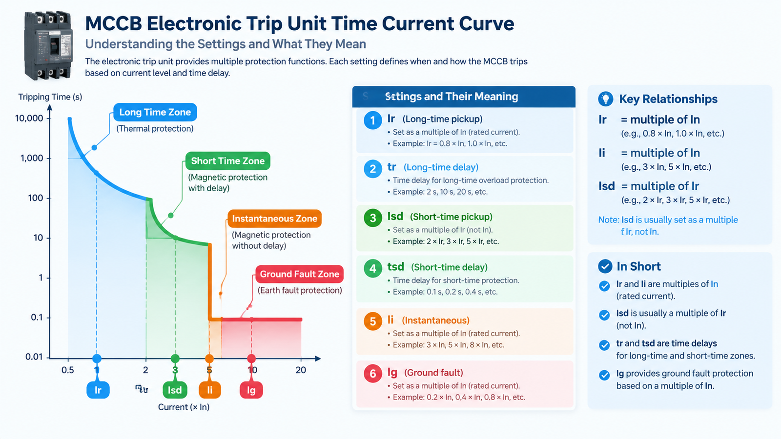
Choosing between a thermal-magnetic and an electronic trip unit is a selection question — one we cover in our MCCB selection guide. This article is about the question that comes after: the breaker is on the panel, the dials are staring at you, and you have to decide what to set Ir, Isd, Ii and Ig to.
Those four settings decide two different things. Ir protects the cable from overloading. Isd, Ii and the delays decide whether a fault on one feeder blacks out one machine or the whole board. Get the first wrong and you cook a cable. Get the second wrong and a fault in a packaging line takes down the plant.
What the Four Letters Actually Mean
Electronic trip units use the same naming convention across most manufacturers, which is helpful once you know it:
Symbole
Fonction
What it protects against
Set relative to
Dans
Sensor or rating plug — the base value every other setting refers to
—
Fixed by the trip unit ordered
Ir (L)
Long-time pickup
Sustained overload
Multiple of In, typically 0.4–1.0
tr
Long-time delay
How long an overload is tolerated
Seconds, usually quoted at 6 × Ir
Isd (S)
Short-time pickup
Moderate fault current, with a deliberate delay
Multiple of Ir
tsd
Short-time delay
The delay that lets a downstream device clear first
Typically 0.05–0.5 s
Ii (I)
Instantaneous pickup
Severe bolted faults, no intentional delay
Multiple of In
Ig (G)
Ground-fault pickup
Earth leakage / insulation failure
Multiple of In, where fitted
There is one subtlety worth internalising: Ir and Ii are usually expressed as multiples of In, while Isd is usually expressed as a multiple of Ir. Confusing the two reference bases is the single most common arithmetic error in trip unit setting, and it produces settings that are wrong by a factor of two or more.
Step 1: Set Ir to the Circuit, Not to the Frame
Ir is the long-time pickup — the current above which the breaker will eventually trip on overload. The instinct is to leave it at 1.0 × In, because that is where it ships. That is usually wrong.
Ir should be set to the design current of the circuit the breaker protects, not to the maximum the frame can carry. A 250 A breaker feeding a 160 A load, left at Ir = 1.0, gives that load no meaningful overload protection at all: the cable would have to carry more than 250 A before the breaker even begins to think about it.
Work the other way round. Establish the design current Ib, confirm the cable can carry it, then select In so that Ib sits comfortably inside the Ir adjustment range, and dial Ir down to Ib. If the load is 320 A, a 400 A sensor with Ir set to 0.8 gives you 320 A — a real overload threshold.
The long-time delay tr is usually an inverse-time characteristic: the higher the overcurrent, the faster the trip. Set it long enough to ride through legitimate inrush — motor starting, transformer energisation — but short enough to stay inside the thermal withstand of the cable.
Step 2: Isd and tsd — Where Selectivity Lives
The short-time zone is what separates a breaker that simply protects from a breaker that coordinates. Isd sets the current above which the short-time function arms; tsd sets how long it waits before acting.
That delay is the whole point. If a fault appears on a downstream feeder, the downstream breaker should clear it. The upstream breaker sees the same fault current, but because its tsd delay is longer than the downstream device’s total clearing time, it waits — and stays closed. Only if the downstream device fails does the upstream breaker trip as backup.
Typical short-time delays run from about 0.05 s to 0.5 s. A commonly used starting point for an upstream MCCB coordinating with downstream MCCBs is 0.2 s, but the correct value comes from the time-current curves, not from a rule of thumb.
Many trip units offer an I²t ON / OFF choice on the short-time delay. With I²t ON the delay shortens as current rises, which limits let-through energy. With I²t OFF the delay is fixed regardless of magnitude, which is easier to coordinate against. Choose deliberately; do not leave it at whatever the factory set.
Step 3: Ii — The Last Resort
The instantaneous function trips with no intentional delay. It exists for severe faults where speed matters more than discrimination.
Set it high enough that normal inrush does not nuisance-trip the breaker, and low enough that it still clears a solid fault on the circuit it protects. On some units the instantaneous function can be switched off entirely — which is how a Category B device achieves a pure time-delayed response. Do not disable Ii unless the coordination study genuinely requires it and the equipment has a declared short-time withstand to carry it.
Step 4: Ig — Ground Fault, If You Have It
Ground-fault protection detects residual current returning through earth. On a four-pole MCCB with a neutral CT, the trip unit summates the phase and neutral currents; any imbalance is leakage.
Ig must be set above the normal leakage and capacitive charging current of the installation, or it will trip on healthy circuits. Large cable runs and variable-frequency drives both generate standing leakage, which is why Ig is normally set with a deliberate delay as well — long enough to let a downstream RCD clear first. For the detection principle itself, see our article on residual current protection.
Worked Example: A 400 A Feeder Off a 630 A Incomer
Say a sub-distribution board is fed from a 630 A incomer, and one of its outgoing feeders supplies a 320 A load over a cable rated 400 A. The feeder is a 400 A frame with an electronic trip unit.
In = 400 A — the sensor matches the cable ampacity.
Ir = 0.8 × In = 320 A — set to the actual design current, with tr chosen to ride through starting inrush.
Isd = 4 × Ir = 1,280 A with tsd = 0.1 s — picks up fault current well above load and inrush, and clears quickly.
Ii = 10 × In = 4,000 A — the bolted-fault backstop.
Now the incomer. For the two to discriminate, the incomer’s short-time delay must exceed the feeder’s total clearing time, and its instantaneous pickup must sit above the prospective fault current at the feeder — or be set high enough that current selectivity holds. In practice: incomer Isd at a comparable multiple with tsd = 0.3 s gives the feeder 0.2 s of margin to clear first.
How Two Breakers Actually Discriminate
Method
How it works
When it applies
Limit
Current selectivity
Upstream instantaneous pickup sits above the maximum fault current at the downstream device
Where there is meaningful cable impedance between the two levels
Fails at high fault levels or with short cable runs
Time selectivity
Upstream short-time delay exceeds downstream total clearing time
Main method on electronic trip units with an S function
Requires the upstream device to have a declared Icw to ride through the delay
Energy selectivity
Comparing let-through I²t of the two devices
Used by some manufacturers for current-limiting breakers
Needs manufacturer-published let-through data
Zone selective interlocking
Downstream device sends a restraint signal to hold the upstream delay
Larger systems where delays would otherwise push arc-flash energy up
Requires a communication link between devices
The critical constraint is the one people discover late: a time delay is only safe if the upstream device can physically survive the fault current for that long. That capability is the rated short-time withstand current, Icw. Most MCCBs have modest Icw values, which is exactly why full time-graded selectivity often pushes a design towards an air circuit breaker at the incomer — a point we work through in MCCB vs ACB.
What You Can and Cannot Set on a Thermal-Magnetic MCCB
A thermal-magnetic unit typically gives you one adjustment — the thermal setting, often 0.7 to 1.0 times the nominal rating — with the magnetic element fixed by the factory or selectable in coarse steps. There is no Isd, no tsd, and no independent Ii.
The practical consequence is that thermal-magnetic breakers achieve selectivity only through current discrimination, and only where cable impedance is generous enough to make fault levels at the two devices differ substantially. Where you need tight, repeatable coordination across several levels, specify an electronic trip unit. Our SNSX 400–630 A et SNS 800–1600 A ranges cover the frames where electronic trip units earn their cost.
Commissioning Checks and Recurring Mistakes
Leaving Ir at the frame maximum. The most common setting error, and it silently removes overload protection from the circuit.
Mixing up the reference base. Isd is usually a multiple of Ir, not In. Check which the dial is calibrated against.
Setting a delay the breaker cannot survive. Confirm Icw before specifying a 0.3 s or 0.5 s short-time delay.
Ignoring inrush. A setting that looks right on paper will nuisance-trip on a motor feeder if tr and Ii do not account for starting current.
Never testing after commissioning. Trip units drift and mechanisms stiffen. A breaker that has not been tested since installation is an assumption, not a protection device.
Setting the values but never recording them. The settings schedule is a deliverable. Without it, nobody can verify coordination later.
Foire aux questions
What is the difference between Ir and In?
In is the rating of the trip unit’s sensor or rating plug — the fixed base value. Ir is the long-time pickup, set as a multiple of In, and it defines the actual overload threshold. In is chosen when the breaker is ordered; Ir is adjusted on site.
Should Isd be set as a multiple of In or Ir?
On most electronic trip units Isd is a multiple of Ir, while Ii is a multiple of In. This varies by manufacturer, so always check the trip unit’s own dial markings or manual before calculating.
Can I switch the instantaneous function off?
Some electronic trip units allow Ii to be disabled to achieve a pure time-delayed response. Only do this where the coordination study requires it and the switchgear has a declared Icw high enough to withstand the fault for the full delay.
Why does my upstream breaker trip before the downstream one?
Because the two are not coordinated at that fault level. Either the upstream instantaneous pickup is below the prospective fault current at the downstream device, or the upstream short-time delay is shorter than the downstream device’s total clearing time. Compare the published time-current curves at the actual fault level.
Do thermal-magnetic MCCBs support selective coordination?
Partially. They rely on current selectivity, which works where cable impedance makes the fault level at the two devices clearly different. They cannot do time-graded coordination because they have no adjustable short-time delay.
Settings Are a Design Deliverable, Not a Dial Position
A breaker with correctly set Ir, Isd, Ii and Ig is a protection device. The same breaker left at factory settings is a switch with a number on it. The difference is a settings schedule produced during design, checked against the time-current curves, and verified at commissioning.
If you are specifying MCCBs for a panel and want the trip unit ranges confirmed against your coordination requirements, send us the single-line diagram and the fault levels. Contact our engineering team and we will confirm which trip unit and frame fits.
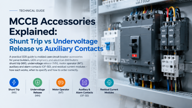
<p>Shunt trip, undervoltage release, auxiliary contacts and motor operators compared - what each MCCB accessory actually does, when to specify it, and the checklist to order the right one first time.</p>
<p>Direct-on-line, star-delta and soft starters compared on starting current, torque, mechanical stress and cost - with the four questions that decide it.</p>
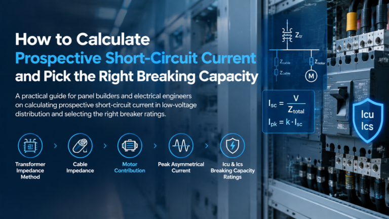
<p>A two-step transformer method for estimating fault level, how cable impedance and motor load change it, and how to turn the result into an Icu/Ics rating.</p>