MCCB Clearance and Arc Venting: A Panel Layout Guide
Why a correctly rated MCCB still fails inspection: what clearance and arc venting actually control in a panel, and how to lay it out before the plate is drilled.
En savoir plus French

An MCCB arrives on site in a sealed carton, is unpacked, checked against the delivery note, and bolted into a panel. In most projects that is the entire incoming inspection, and the first real test the device gets is the day a fault occurs — which is a poor moment to discover that the trip unit was damaged in transit or that the wrong rating was shipped.
The opposite failure is just as common: a contractor arrives with a full test kit, performs a dielectric test at a voltage the device was never intended to see, and damages insulation that was perfectly good. Both mistakes come from the same gap — not knowing which checks belong on site and which belong in a factory or a laboratory.
This article sets out what a panel builder can usefully verify before installation, what the readings actually mean, and what must be left to the manufacturer. The checks are the ones that need no specialist certification, only a meter, a torque wrench, and a record sheet.
An MCCB is type-tested to IEC 60947-2. That testing establishes breaking capacity, trip characteristics, dielectric withstand, and mechanical endurance on a sample — and it is done by the manufacturer, on calibrated equipment, at currents a site cannot produce.
Nothing you do on site repeats any of it. A site check answers a narrower and more practical set of questions:
What a site check cannot establish is the shape of the tripping curve, the actual breaking capacity, or whether an electronic trip unit still meets its accuracy specification after a drop. Those require injection equipment or a return to the manufacturer, and no amount of field testing substitutes for them.
Most defects that reach a panel are visible before anything is energised. The inspection has to be done against the purchase order, not against the carton label, because a mis-shipment is exactly the case where the two disagree.
Work through this in order, with the device still out of the panel:
Record the result per device, not per batch. In a panel with twenty breakers, the one that was dropped in transit will be the one nobody wrote down.
The mechanism check is quick and it catches damage that visual inspection misses.
Operate the device manually through several complete cycles. Close, open, close again. The handle should travel without binding, the indication should be unambiguous at both ends, and the effort should feel consistent from the first cycle to the fifth. A device that closes easily on the first operation and stiffens by the fifth has something wrong inside.
Use the trip button. Pressing the test or trip button should release the mechanism and show the tripped indication, which is mechanically distinct from the open position on most devices. Reset must require a deliberate movement — if the handle simply springs back to the closed position, the mechanism is not latching correctly.
Check trip-free behaviour if the device offers it. On a trip-free mechanism, holding the handle in the closed position does not prevent the device from tripping on a fault, and the handle ends in the tripped position rather than being forced closed. This is a safety characteristic and it is worth confirming on one sample per batch rather than assuming it from the datasheet.
On motor-operated or remotely controlled devices, operate the mechanism through its full electrical cycle before it goes into the panel. A motor operator that stalls at the end of travel will do it inside a closed enclosure, where the sound is muffled and the symptom looks like a control problem. The control circuit itself — coil voltage, spring-charge indication, limit switches — belongs to the switchgear, and the settings that make it behave predictably are covered under trip unit and control settings.
This is the test most often done wrongly, in both directions — skipped because it is inconvenient, or performed at a voltage that damages the device.
An insulation resistance test applies a direct voltage between live parts and earth, or between poles, and measures the resistance. For low-voltage devices the test voltage is commonly 500 V DC, and the value to apply is the one in the manufacturer’s instruction sheet for that device, because the insulation system — not the tester — sets the limit. Applying a higher voltage to “be thorough” stresses insulation that was never designed for it, and the damage is progressive rather than immediately visible.
Practical points that change the result more than the device does:
Where the reading is low, isolate before concluding. Remove the outgoing cables and re-test the device alone. Half the “faulty breaker” reports in a commissioning file end at this step.
A micro-ohmmeter or a low-resistance tester passes a known direct current through one pole at a time and measures the voltage drop across it. The absolute value depends on the frame, the current used, and the meter, so it is not a number to compare against a table. The useful information is the comparison between the three or four poles of the same device, measured the same way.
A single pole reading markedly higher than its neighbours has a contact problem: a damaged contact, a foreign body, or a mechanism that is not closing fully on that pole. All poles reading high together points at the measurement — wrong current, poor probe contact, or a device that is not fully closed.
Two conditions make the measurement meaningless, and both are easy to create on site:
Where a device is supplied with a manufacturer’s test record, compare your readings against it before deciding anything. A pole that matches the factory record is not a pole with a problem, however much the number differs from a rule of thumb.
Three things are routinely attempted on site and should not be.
Trip characteristic verification. Confirming that the device trips at 1.3 times Ir within the specified time, or that the instantaneous element operates at the right multiple, requires a primary injection set capable of passing hundreds or thousands of amperes through the device and timing the operation. Nothing in a panel builder’s toolkit does this, and a device that trips “when tested with a small current” has not been verified at all.
Capacité de rupture. Icu and Ics are established by test at the manufacturer. There is no field check. The number on the nameplate is the only evidence you will have, which is why the nameplate-to-order comparison in the incoming inspection matters so much.
Electronic trip unit accuracy and protection function testing. Some trip units offer a self-test or a secondary injection port, and using it is legitimate — but it verifies the electronics, not the current path, and the procedure is the manufacturer’s, at the manufacturer’s test points. Where a device has been dropped, or has been in storage for years, the correct action is a return for verification, not a field adjustment.
Repair is in the same category. An MCCB is a sealed, type-tested assembly. Opening the case to clean contacts or adjust a mechanism voids the verification the device was sold with, and no site procedure restores it.
The table below is the sequence to work through, in the order the checks become possible. Everything before the “after wiring” block can be done on the bench, before the device is mounted.
| Stage | Vérifier | Méthode | Reject if |
|---|---|---|---|
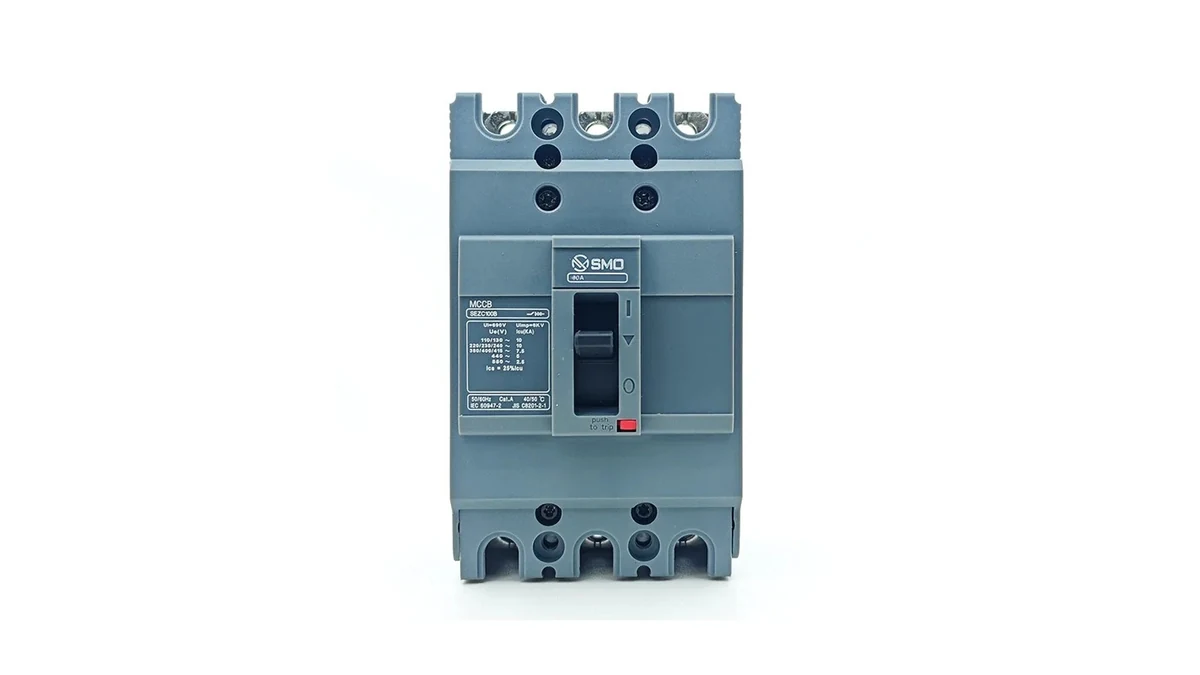
| On receipt | Rating, poles, breaking capacity, trip unit type | Nameplate against purchase order | Any mismatch, however small |
| On receipt | Moulding and terminal condition | Visual, with a light into the terminal wells | Crack at a terminal well, corrosion, cross-threaded stud |
| On receipt | Arc chute and exhaust clear | Visual inspection of the exhaust openings | Displaced segment, packing material, swarf |
| On receipt | Accessories present | Against the order line by line | Any accessory missing or loose |
| Before mounting | Mechanism operation | Five manual cycles, trip button, reset | Binding, inconsistent effort, no distinct trip indication |
| Before mounting | Trip unit settings | Dial positions against the order, seals intact | Settings differ from the order |
| Before mounting | Contact resistance | Micro-ohmmeter, pole by pole, conductors removed | One pole markedly above its neighbours |
| After wiring | Insulation resistance | 500 V DC per the instruction sheet, electronics isolated | One pole consistently low after cables are removed |
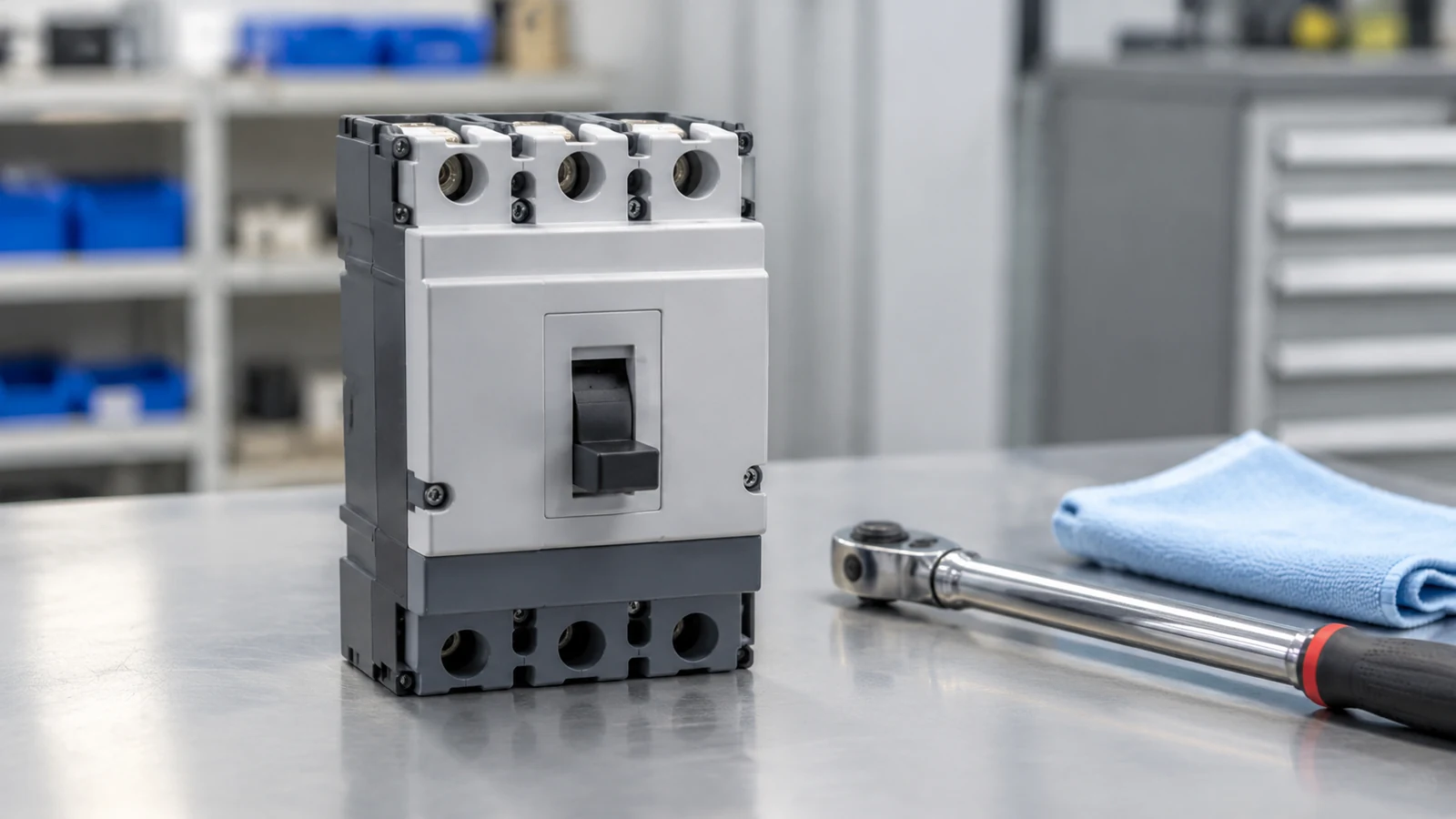
| After wiring | Terminal torque | Calibrated torque wrench to the published value | Value not reached, or reached only by over-torque |
Two entries in that table are worth emphasising because they are skipped most often. The arc chute check is invisible after mounting, and the torque value is the only item on the list that cannot be verified later by inspection — a joint that was under-torqued looks exactly like one that was not.
A pre-installation check without a record is a conversation, not a test. The record needs four things per device: the serial or order reference, the checks performed, the readings taken, and the person who took them. That is enough to settle a warranty discussion months later, and it costs a few minutes per panel.
When a check fails, the response depends on which check it was:
None of these outcomes requires opening the device. That is the dividing line: everything a panel builder can legitimately do stops at the outside of the case.
No. Verifying the curve requires primary injection at multiples of the rated current and timing the operation, which needs equipment a panel builder does not have. What you can do is confirm that the nameplate rating and trip unit settings match the design, and that the mechanism trips and resets correctly.
The value in the manufacturer’s instruction sheet for that device — commonly 500 V DC for low-voltage devices, but the insulation system sets the limit, not the tester. Electronic trip units and control modules are isolated or removed before the test, and a higher voltage applied “to be safe” can damage insulation that was sound.
Not mandatory, but it is the only check that detects a poor internal contact before the device is in service, and it takes a few minutes per device. If you do it, measure pole to pole on the same device and compare — the absolute value is far less useful than the difference between poles.
No. Opening an MCCB breaks the seal on a type-tested assembly, and there is no field procedure that restores the verification. A device with contaminated contacts goes back to the manufacturer or into scrap.
Treat it as suspect even if it looks undamaged and operates freely. Impact damage can displace an arc chute segment or disturb a trip unit without any external mark. Return it for verification, or replace it — the cost of one device is small against a panel that trips unpredictably.
The checks above take a few minutes per device and they all happen before the panel is closed, which is the only time they are cheap. They do not replace type testing and they do not verify the trip curve — they close the gap between “the right device was ordered” and “the right device is installed and undamaged”.
Device data, including terminal torque values and the accessory list per frame, is published on our moulded case circuit breaker page. Once the panel is in service, the MCCB maintenance schedule covers the checks that only make sense after energisation, and the selection steps explain how the rating was arrived at in the first place. If you are writing an incoming inspection procedure for a project, send us the device list and we will confirm which checks apply to each frame, and which of them the factory test record already covers.