Calendrier d'entretien et d'inspection des disjoncteurs MCCB : ce qu'il faut vérifier et à quel moment
Publié le : Auteur : Rachel
An MCCB is bought as a maintenance-free component and then spends fifteen years in a panel that nobody opens. That works more often than it should, which is exactly why the failures that do happen arrive without warning: a breaker that has been sitting closed at 70% load in a dusty enclosure since commissioning does not announce that its contacts have been eroding, or that a terminal screw has been slowly losing torque since the day the panel was built.
A maintenance schedule for moulded-case breakers is not a long document. It is a short list of checks, performed at an interval that matches the duty and the environment, with the results written down so the next check has something to compare against. The difficult part is not the checks themselves — it is knowing which few things can actually be inspected on a sealed device, which measurements mean something, and which parts of the breaker must never be opened in the field.
This article sets out a practical MCCB maintenance checklist, how to set the interval from duty and environment, how to interpret contact resistance and insulation resistance results, what trip testing can and cannot prove on site, and the specific actions that turn a serviceable breaker into a warranty claim.
What Maintenance Actually Means for a Moulded-Case Breaker
The name is literal: the case is moulded around the mechanism, and it is not designed to be opened. Contacts, arc chutes, the operating mechanism and the trip element sit inside a sealed enclosure that was type tested as an assembly. Opening it invalidates that test and, on most products, the warranty.
So the maintenance task is not repair. It is four things:
Inspection — looking for the conditions that predict failure: heat discolouration, cracking, moisture, dust bridging, loose terminations, corrosion at the connections.
Verification — confirming that the device still operates mechanically, that the trip mechanism has not seized, and that insulation and contact resistance are within limits.
Measurement — recording values so that a trend exists. A single millivolt drop reading tells you little; the third reading, two years later, tells you a lot.
Decision — replacing a device that has failed a check, rather than adjusting something to make the check pass.
That last point separates a maintenance programme from a habit of fiddling. On a sealed device, the only legitimate outcome of a failed check is replacement, plus an investigation into why it failed. There is no field repair.
Setting the Inspection Interval From Duty, Environment and Criticality
Manufacturers publish recommended intervals, and they are a reasonable starting point, but the interval that matters is the one your installation justifies. Four factors move it:
Factor
What pushes the interval shorter
Practical effect
Load relative to rating
Continuous operation above roughly 70–80% of the rating, or high harmonic content
More thermal cycling in the terminals and more contact wear; halve the interval
Terminal corrosion and insulation surface tracking appear long before the breaker fails outright
Switching duty
Frequent manual or motor-operated switching, or use as a daily isolator
Mechanical wear on the mechanism and the main contacts; the electrical life figure becomes relevant
Criticality
The breaker is an incomer, feeds a process line, or protects a circuit where a spurious trip is expensive
Shorter interval and full measurement, because the cost of an unplanned trip dominates the cost of inspection
A workable default for an ordinary distribution board in a clean, temperature-controlled room is an annual visual and mechanical inspection, with measurement every second or third year. Add a visual check at six months in a workshop, a foundry or anywhere the enclosure is opened regularly. Add an immediate inspection after any trip that was not an overload — a short-circuit trip is an event that puts the device through a duty it may only survive a limited number of times.
Two triggers override the calendar entirely. Any breaker that has cleared a fault near its rated breaking capacity should be inspected, and considered for replacement if the fault was at or above the value the device was selected for. And any breaker that has been sitting in a panel with visible moisture ingress should be checked before it is relied on again, regardless of when it was last seen.
The Visual and Mechanical Check
This is the part that finds most developing failures, and it needs no instruments beyond a torque wrench and a torch. Work with the panel isolated and locked off, and treat the breaker’s own handle position as the first data point.
Confirm the handle indicates what actually happened. A breaker that tripped electrically sits in a distinct middle position on most designs, not in the OFF position. A handle forced to OFF after a trip can mask a fault that has not been found. If the handle is in the tripped position, find out why before resetting.
Look for heat at the terminations. Discolouration of the cable insulation at the lug, browning of the moulding around a terminal, or a hardened, brittle crimp are all signs of a joint that has been running hot. The cause is usually torque loss or an undersized lug, not the breaker.
Check the case for cracks, chalking or deformation. A crack in the moulding is a replacement, not a repair. Chalking on the surface suggests UV or chemical attack. Deformation around a pole suggests the device has been overheated internally.
Inspect for dust bridging and moisture. Conductive dust across the top of a breaker, combined with condensation, is a tracking path. Clean with a dry, lint-free cloth or vacuum; do not use solvents that attack the moulding.
Operate the mechanism several times. The handle should move positively through its full travel, with a clear snap and no binding. A mechanism that feels sluggish or sticks has usually been sitting unused in a damp enclosure.
Use the trip test button if the device has one. Many MCCBs carry a mechanical test button that unlatches the mechanism without current. It proves the latch releases and the mechanism opens — nothing else. Confirm afterwards that the breaker resets and that the handle returns to the correct position.
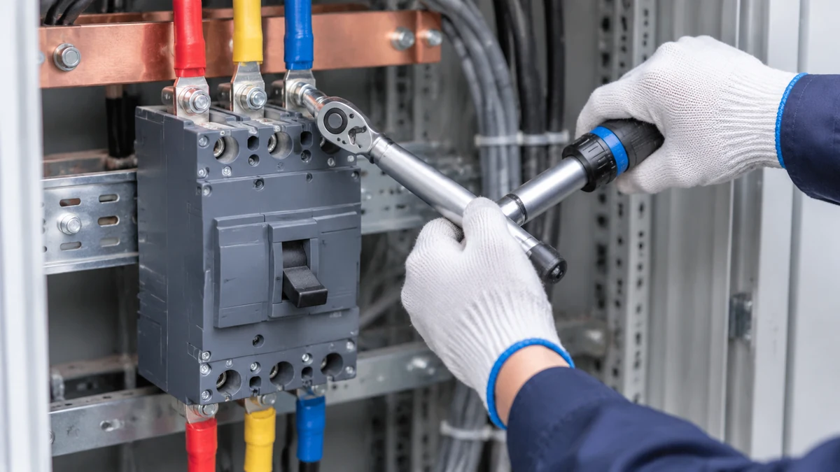
Check terminal torque against the manufacturer’s figure. Not “tight”. The specified torque, with a calibrated wrench, on every terminal. This single step prevents more failures than everything else on the list combined.
Contact Resistance and Millivolt Drop
Contact erosion is invisible from outside, and it is the mechanism by which a breaker that has never tripped starts to run warm. The measurement that tracks it is the resistance across a closed pole, taken with a micro-ohmmeter or by the millivolt drop method with a low test current.
Three rules make the result usable:
Measure all poles in the same session. The comparison between poles is often more informative than the absolute value: one pole reading significantly higher than the other two is a developing problem even if all three are within the manufacturer’s limit.
Compare against the manufacturer’s value, and against the previous reading. Manufacturers publish a maximum resistance or millivolt drop per pole. Where that figure is available, it is the acceptance criterion. Where it is not, a rising trend across successive inspections is the signal.
Record the test current and the ambient temperature. Resistance is temperature dependent, and a value taken in a cold panel in winter is not directly comparable with one taken in August.
A useful practical rule is that a pole reading materially higher than its siblings, or a reading that has climbed noticeably since the last inspection, warrants replacement rather than another year of watching. On a sealed device there is nothing to clean or adjust to bring the number back down.
Insulation Resistance Testing
Insulation resistance checks the integrity of the insulation between phases and between phase and earth — the barrier that keeps a polluted, damp breaker from becoming a fault path. It is a simple test, and it is easy to do badly.
The procedure that gives a meaningful result:
Isolate and lock off, prove dead, and disconnect or isolate sensitive downstream equipment — electronics, surge protection devices, anything with a semiconductor front end. An insulation tester will damage them.
Open the breaker. Test with the contacts open, so the measurement covers the insulation and not the closed contact path.
Use a DC test voltage appropriate to the system — 500 V DC is the usual choice for a 400/230 V installation. Higher test voltages are not automatically better and can stress aged insulation.
Measure phase-to-phase and each phase to earth, and record every value with the test voltage and the ambient conditions.
Apply the acceptance threshold from the standard or specification that governs the installation, or from the manufacturer’s data. A value around 1 MΩ at 500 V DC is a common practical floor for acceptance in low-voltage assemblies, but the governing document is the one to cite.
Two cautions. A low reading is not automatically a failed breaker — moisture on the surface of the moulding produces the same result and disappears after the panel is dried and the test repeated. And a high reading does not prove the contacts are healthy; that is what the resistance measurement is for. The two tests answer different questions and neither replaces the other.
Trip Testing: What Can Be Proven On Site and What Cannot
This is where expectations usually exceed what is possible. A trip test on site proves that the breaker will open. It does not, in general, prove that it will open at the right current.
Device type
What can be verified on site
What cannot
Thermal-magnetic MCCB
Mechanical trip via the test button; that the mechanism unlatches and resets; handle position after a trip
Actual thermal and magnetic thresholds — these require primary current injection with equipment most sites do not have, and the device is not adjustable to compensate
Electronic trip MCCB
Self-test and status indication; settings read back and compared against the design; secondary injection where the trip unit supports it and the test kit is available
Whether the current sensors and the interruption path are healthy — that still needs primary injection or a replacement decision
For an electronic trip unit, the self-monitoring function is worth using as a routine check: most units indicate a healthy state on a status indicator and will flag an internal fault. Reading the settings back and comparing them against the design document is a five-minute check that catches the most common real-world problem, which is not a failed trip unit but a setting that was changed during commissioning and never recorded. The relationship between the settings and the protection they deliver is covered in the guide to trip unit settings and their verification.
Where the circuit is critical enough to justify primary injection, that is a specialist service with a test set capable of injecting several times the rating. It is worth doing at commissioning and at long intervals on incomers that protect a whole plant. It is not something to attempt with a clamp meter and a load.
What Must Never Be Opened or Adjusted in the Field
The list is short and every item on it has been responsible for a failure somewhere:
Do not open the moulded case. The arc chutes, contacts and mechanism are a type-tested assembly. Once the case is open, the device is no longer the product that was certified, and no amount of reassembly restores that.
Do not adjust the calibration. Thermal-magnetic breakers have no user adjustment for a reason. Turning a calibration screw to stop nuisance tripping converts a protection device into an unverified switch.
Do not raise Ir or Isd to solve a nuisance trip. A breaker that trips on a legitimate overload is reporting a problem in the circuit. Changing the setting moves the problem to the cable. If the setting genuinely does not match the design, that is a design correction with a documented calculation, not a field adjustment.
Do not lubricate the mechanism with general-purpose grease. The mechanism is lubricated for life with a specific product. Adding an incompatible grease attracts dust and can stiffen with age.
Do not file or dress the contacts. There is no access, and no field procedure that restores a contact surface to its tested geometry.
Do not bypass the device, bridge a pole, or hold the handle closed. Every one of these has been done, and every one of them removes the protection the circuit was designed around.
Do not reuse a breaker that has cleared a heavy fault without assessing it. A device that has interrupted a current near its breaking capacity has absorbed significant energy. Inspect it, and replace it if there is any doubt.
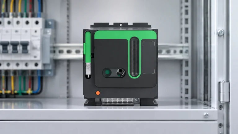
Accessories deserve a separate note. Shunt trips, undervoltage releases and auxiliary contacts are user-installable on most ranges and are designed to be added or replaced in the field. Their wiring is part of the control circuit and should be checked at the same interval — a shunt trip whose coil has failed open will not trip the breaker remotely, and nothing on the breaker will indicate it. The behaviour of these accessories is set out in the guide to shunt trip and undervoltage release accessories.
Keeping a Record That Makes the Schedule Useful
A maintenance schedule without records degrades into a visual glance once a year. The record is what turns a check into a trend, and it needs only a handful of fields per device:
Panel, circuit and device identifier, with the rating and the settings as found.
Date, ambient temperature, and the load at the time of inspection.
Insulation resistance per pole and to earth, with the test voltage.
Contact resistance or millivolt drop per pole.
Terminal torque result — pass or the value found.
Visual findings, in plain words: “slight discolouration at L2 lug”, not a tick.
The decision taken, and by whom.
Two additions make the record considerably more valuable. Thermal imaging under load, taken at the same time each year, gives a picture of every joint in the panel in ten minutes and is the fastest way to find a hot termination before it fails; store the images with the readings. And a note of any trip event since the last inspection, with the presumed cause — that is the single most useful piece of history a breaker has.
Interval, method and record-keeping all reduce to one question: if this breaker fails to operate when it is needed, what would you have wished you had checked? For most installations the answer is the terminations, the mechanism, and whether the device has been quietly cooking for years — all three of which are visible or measurable without opening anything.
Foire aux questions
How often should an MCCB be inspected?
Annually is a reasonable default for a clean, temperature-controlled distribution board, with measurement every second or third year. Shorten it to six months in dusty, humid or corrosive environments, where the panel is switched frequently, or where the breaker is an incomer feeding a critical process. Inspect immediately after any short-circuit trip, regardless of the calendar.
Can an MCCB be repaired on site?
No. The case is sealed and the current-carrying and interrupting parts are not serviceable in the field. A device that fails a check is replaced, and the reason for the failure is investigated separately — a hot terminal or a cracked case is usually a symptom of a panel problem rather than a defective breaker.
What insulation resistance value is acceptable?
Apply the threshold from the standard or specification governing the installation, or the manufacturer’s data. Around 1 MΩ at 500 V DC is a widely used practical floor for low-voltage assemblies. A low reading should be investigated before the breaker is condemned: surface moisture and dust on the moulding produce the same result and often disappear once the panel is dried and the test repeated.
Does the test button prove the breaker will trip on a fault?
No. The mechanical test button proves that the latch releases and the mechanism opens. It says nothing about whether the thermal element will respond at the right current, or whether the magnetic threshold is where the label claims. Proving the thresholds requires primary current injection, which is a specialist service rather than a routine check.
Is thermal imaging a substitute for the electrical checks?
It is a screening tool, not a substitute. Thermal imaging under load finds hot joints and uneven phase loading quickly and safely, and it is excellent for prioritising which panels need attention. It cannot tell you the contact resistance of a pole, the insulation resistance, or whether a trip mechanism has stiffened — those still need the instrument checks.
When should a breaker be replaced rather than kept in service?
Replace it when the case is cracked or deformed, when a pole’s contact resistance is materially above its siblings or above the manufacturer’s limit, when the mechanism binds, when insulation resistance stays low after drying, or when the device has cleared a fault near its rated breaking capacity. Age alone is not a criterion — a correctly applied breaker in a clean panel can serve for decades — but age combined with any of the above is.
If you are specifying replacement devices for an existing panel and the original range is no longer available, the ratings that have to match are set out in the guide to choosing the right MCCB for the duty, and the moulded case circuit breaker product range lists the frames and breaking capacities available now. Send the existing nameplate details through the contact form if you need the closest current equivalent confirmed.
Pourquoi le rapport fusible/disjoncteur de puissance ne s'applique que dans un seul sens, dans quels cas la méthode du rapport échoue, et comment vérifier la sélectivité à l'aide d'un tableau de coordination publié.
Un actionneur motorisé transforme un disjoncteur à boîtier moulé à commande manuelle en un dispositif pouvant être actionné à distance. Il se fixe à l'avant du disjoncteur, s'engage sur la même poignée que celle que l'électricien actionnerait, et arme et relâche le ressort à énergie emmagasinée sur commande. Les caractéristiques de protection du disjoncteur restent inchangées : l'unité de déclenchement, les courbes et la capacité de coupure […]
Un circuit moteur est le seul endroit d'un tableau électrique où deux dispositifs de protection sont montés en série et prétendent tous deux protéger le même élément. Le disjoncteur miniature (MCCB) situé dans le circuit d'alimentation et le disjoncteur miniature à coupure mécanique (MPCB) situé dans le boîtier du démarreur ne sont pas interchangeables, mais leurs fonctions se recoupent suffisamment pour que, dans certains tableaux, l'un soit installé à la place de l'autre — […]