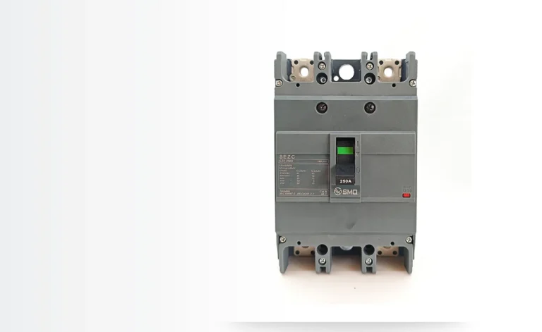
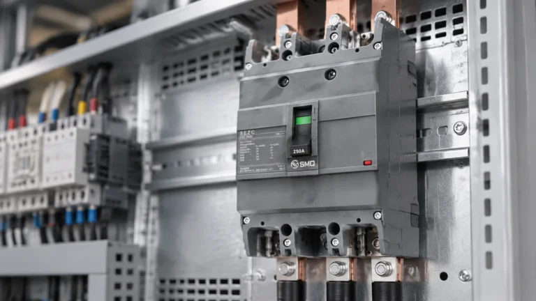
MCCB Frame Size vs Trip Rating: Why a 250 A Frame Can Carry 160 A
Publié le : Auteur : Rachel
A 250 A frame carrying 160 A looks like a mistake on a drawing. It is usually the opposite: it is what happens when someone has read the catalogue properly and separated three numbers that a datasheet prints side by side and that a lot of specifications still treat as one.
The three numbers are the frame size, the rated current of the device and the trip setting. They are related but not interchangeable, and the relationship between them is what lets a single 250 A frame serve a 100 A circuit, a 160 A circuit and a 250 A circuit with the same external dimensions.
Getting this wrong is expensive in both directions. Oversize the trip rating and the cable is unprotected. Undersize the frame and you lose breaking capacity, terminal capacity or simply the ability to fit the cable lug. This article sets out what each number means, works a 160 A example through to a device selection, and lists the places where the frame is deliberately chosen larger than the load.
MCCB Frame Size vs Rated Current: Three Numbers on One Device
Every MCCB datasheet carries at least three current values, and the naming differs slightly between manufacturers. The definitions below follow IEC 60947-2 terminology, with the common catalogue symbols in brackets.
Value
Symbol in catalogues
What it describes
Taille du cadre
Often written as the frame class, e.g. “250 A frame”
The mechanical platform: moulding dimensions, terminal size, pole pitch, and the maximum current the platform is built to carry
Rated uninterrupted current
Iu
The current the device can carry continuously at the reference ambient, without regard to the trip setting
Rated current of the device
In (sometimes Inm)
The rating of the specific variant — the sensor and trip element fitted in that frame
Long-time trip setting
Ir
The actual overload set point, adjustable on electronic trip units and fixed or narrowly adjustable on thermal-magnetic ones
Capacité de rupture
Icu / Ics
Short-circuit withstand and breaking capability at a stated voltage — a function of the frame and the variant, not of Ir
On a thermal-magnetic device the frame and the rating are usually sold together: a 250 A frame with a fixed 250 A bimetal. On an electronic device they separate cleanly, because the trip unit is programmable and the same frame can be supplied with several sensor ratings.
What the Frame Actually Fixes
The frame is the mechanical and thermal envelope. Choosing it determines things that cannot be changed later by turning a dial:
Terminal capacity. A 250 A frame accepts a range of cable lugs and busbar thicknesses. A 100 A frame in the same family often will not take the cable you have already specified.
Available breaking capacity. High Icu variants are usually built on the larger frames in a family. If the prospective fault current is high, the frame may be forced upward even when the load is small.
Heat dissipation and pole pitch. The larger the frame, the more copper and the more surface area, which is why a larger frame runs cooler at the same current.
Panel space and accessory fit. Motor operators, shunt trips, auxiliary contacts and terminal shrouds are frame-specific. Move up a frame and the accessory list changes.
Available ratings. A family might offer a 250 A frame in 100, 125, 160, 200 and 250 A ratings — five products, one set of drawings.
That last point is the reason the 160 A circuit in the example ends up on a 250 A frame. It is not that the frame is oversized; it is that the frame is the smallest one in the family that offers the rating, the breaking capacity and the terminal size the job needs.
Rated Current In Is Not the Trip Setting
In is the rating of the device as manufactured and type tested. Ir is where the long-time protection actually begins. On a fixed thermal-magnetic breaker they are the same number, because the bimetal is made for that rating. On an electronic trip unit, Ir is a fraction of In — typically adjustable from 0.4 to 1.0 In in steps.
This is where most of the confusion on drawings comes from. A 250 A frame with a 250 A rating and Ir set to 0.64 is, for protection purposes, a 160 A device. Its thermal curve sits where a 160 A breaker’s would sit; its instantaneous threshold sits at a multiple of the setting or of In depending on how the manufacturer defines Ii; and its breaking capacity is still the 250 A frame’s breaking capacity.
Rule of thumb: the frame decides what the device can survive, In decides what the sensor can measure, and Ir decides what the circuit is protected against. Only Ir protects the cable.
Worked Example: A 160 A Feeder on a 250 A Frame
Take a feeder with a design current of 160 A, a corrected cable capacity of at least 160 A, and a prospective fault current of 25 kA at the breaker terminals. The design steps run in this order:
Fix the protection level from the cable, not the load. The long-time trip setting must be above the design current and below the corrected cable capacity, with the standard overload relationship respected. Ir = 160 A is the natural choice when the cable is sized on the load.
Check breaking capacity at the system voltage. 25 kA prospective means Icu of at least 25 kA at 415 V, with Ics checked separately — Ics is the value the breaker can break repeatedly, and it is normally lower than Icu.
Pick the frame that delivers both. If the 160 A frame in the family is only offered at 18 kA, the 250 A frame is required, not optional. That is the first legitimate reason for the mismatch.
Confirm the terminal. A 160 A feeder is often 95 mm² copper. Check the lug range on the frame you have chosen, and check the busbar thickness if the feeder lands on a bar.
Set Ir to the cable protection value. On an electronic unit with In = 250 A, Ir = 0.64 gives 160 A. On a thermal-magnetic 250 A device there is no such option — which is exactly why the electronic variant exists in this size band.
The result is a device whose nameplate reads 250 A and whose protection curve reads 160 A. Both readings are correct. The nameplate describes the hardware; the curve describes the protection.
Why Deliberately Oversizing the Frame Is Normal
Five situations make a larger frame the right answer rather than a conservative one:
Situation
What forces the larger frame
What you gain
High prospective fault current
The small frame is not offered at the required Icu
Breaking capacity, without changing the protection setting
Large cable or busbar termination
Terminal and lug range on the small frame is insufficient
Correct torque and contact area, no adapter plates
Hot enclosure
Derating takes the small frame below the design current
Thermal headroom, at the cost of panel space
Future load growth
Ir can be raised later without replacing hardware
One device covers two design stages
Selectivity with downstream devices
Frame size sets the available setting ranges and the short-time options
A grading margin that ratio rules alone cannot provide
Note what is missing from that table: “because 250 A sounds safer than 160 A” is not on the list. An oversized frame with the wrong Ir setting protects nothing, and an oversized frame with the right Ir is simply a more expensive way to reach the same curve.
The Mistakes This Terminology Causes
Four errors show up repeatedly in panel schedules and in purchase orders:
Reading the frame as the rating. A schedule that says “250 A MCCB” against a 160 A feeder is ambiguous. State In and Ir separately, or state the variant’s rating and the setting.
Raising Ir because the frame is bigger. The most common field error on electronic units: the installer sees a 250 A device and sets Ir to 1.0. The cable is then protected at 250 A while being rated for 160 A.
Assuming Icu travels with Ir. Breaking capacity belongs to the frame and variant, not the setting. Lowering Ir does not increase Icu, and the breaking capacity test is performed at the device’s rating, not at the dialled setting.
Ignoring derating on the setting. If the enclosure runs at 55 °C, the frame’s thermal capacity falls. On a thermal-magnetic device the whole curve shifts with it; on an electronic device the measurement is largely unaffected but the device’s own continuous rating still derates. Either way, a 160 A setting inside a hot enclosure is not the same installation as one in a cool one.
The derating side of this is a separate calculation, set out in our guide to choosing the right MCCB. Frame selection and rating selection have to be done together, but they are answered by different tables.
How the Choice Changes the Price
Frame size is one of the largest single drivers of MCCB cost, because it determines how much copper, moulding and breaking capacity you are buying. Moving from a 160 A frame to a 250 A frame at the same breaking capacity typically adds a meaningful step in price, and moving to a high-Icu variant of the larger frame adds another.
That is why an electronic trip unit on a large frame can still be the cheaper total solution: paying once for a frame that covers two ratings is often less than paying twice for two fixed-rating devices, before spares are counted. The structure of an MCCB quotation shows how frame, breaking capacity and trip type stack up in the price.
Checklist Before You Put a Number on the Drawing
Vérifier
Question to answer
Protection setting
What Ir does the cable require, after correction factors?
Device rating
What In will you order, and does the trip unit’s Ir range include the value you need?
Capacité de rupture
What are Icu and Ics at the actual system voltage, and does the required variant exist in the frame you want?
Termination
What cable or busbar arrives at the terminals, and is it inside the frame’s range?
Ambient
What is the temperature at the breaker, and what does the derating table do to the continuous rating?
Accessories
Do the shunt trip, auxiliary contacts or motor operator you need exist for this frame?
Spares
Does the stocked spare cover this rating at the required setting, or do you need a second part number?
FAQ
Can a 250 A MCCB protect a 160 A cable?
Only if its long-time setting is at or below the cable’s corrected capacity. A fixed 250 A thermal-magnetic device cannot: its curve starts at 250 A and the cable is under-protected. A 250 A frame fitted with an electronic trip unit set to Ir = 160 A can, because the protection curve is then the 160 A curve even though the hardware is rated 250 A.
Why is the frame rating sometimes printed as a range?
Because one frame is sold in several ratings. Markings such as “200/400 A” indicate the frame accepts either a 200 A or a 400 A trip element; the frame class itself is a single mechanical platform. Always confirm which rating the unit you receive actually carries, and check the nameplate rather than the carton.
Does a larger frame improve selectivity?
It can, indirectly. Larger frames offer wider setting ranges and, on electronic versions, a short-time delay that a smaller frame may not have. But selectivity comes from the settings and the manufacturer’s verified tables, not from the frame size alone. Two devices of the same frame can be fully selective if their curves are graded properly.
Is a higher frame rating always better for heat?
A larger frame dissipates heat better and carries more current for the same temperature rise, so it reduces thermal stress on the device. It does not reduce the heat in the enclosure — the load current is the same. If the panel is hot, the fix is ventilation or a larger enclosure, not a bigger breaker alone.
Deux disjoncteurs MCCB figurent côte à côte sur un devis. Même châssis, même capacité de coupure de 36 kA à 415 V, même nombre de pôles, même disposition des bornes. L'un est proposé à un prix supérieur de 30 à 40 % à celui de l'autre, et la ligne qui explique cet écart tient en un seul mot dans la description : type de déclenchement. Thermomagnétique ou électronique […]
Un disjoncteur à boîtier moulé de 250 A ne supporte pas un courant de 250 A. Il ne supporte 250 A que dans des conditions spécifiques qui ne sont pas précisées sur la plaque signalétique : une température ambiante donnée, un espace libre autour de l’appareil, un seul disjoncteur monté verticalement, et l’absence de boîtier limitant la convection. Si l’une de ces conditions change, alors […]
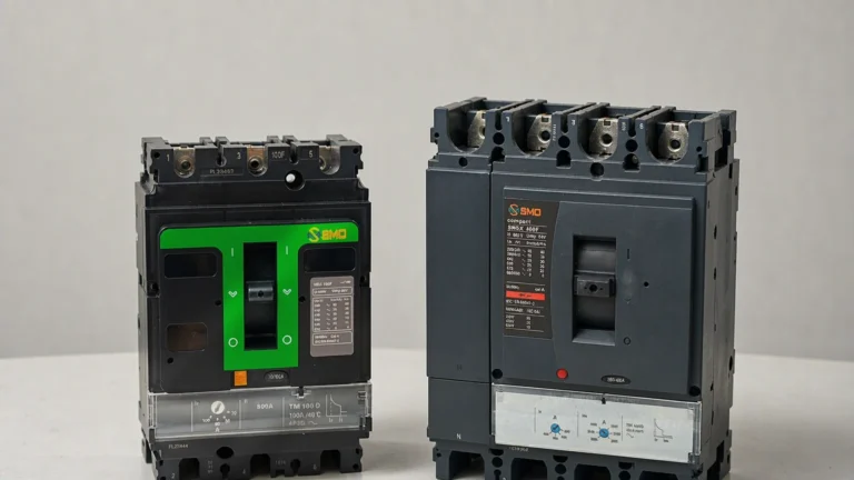
Deux disjoncteurs MCCB sont montés côte à côte dans un tableau. Tous deux sont des modèles de 250 A, tous deux ont une capacité nominale de 36 kA à 415 V, et proviennent tous deux de la même page du catalogue. L'un est tripolaire, l'autre quadripolaire. La différence de prix n'est pas ce qui nous intéresse ici. La question à laquelle il convient de répondre est de savoir si ce quatrième pôle remplit une fonction quelconque, […]