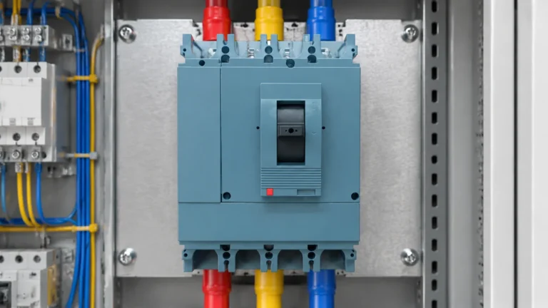
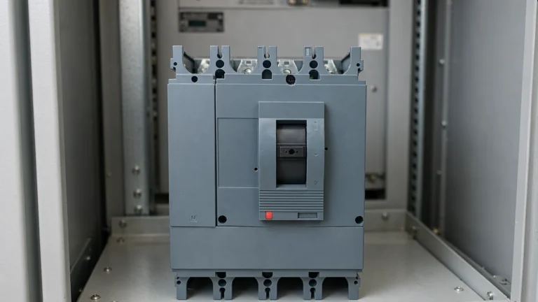
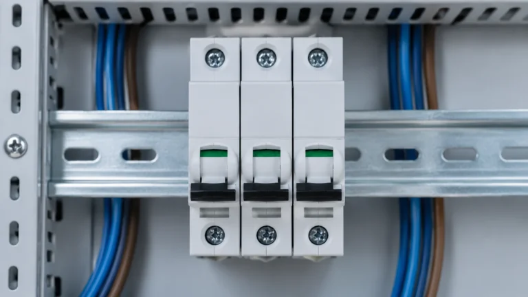
Testing an MCCB Before Installation: What Can Be Checked on Site
What a panel builder can genuinely verify on an MCCB before installation, what the readings mean, and what must be left to the manufacturer.
En savoir plus French

Ask two panel builders to protect twelve final circuits and you will get two different boards. One has twelve MCBs and two shared RCDs. The other has twelve RCBOs and nothing else. Both pass inspection, both meet the same requirement for earth-fault protection, and they differ in width, cost, fault-finding time, and what happens to the other eleven circuits when one develops a leak.
The comparison is usually reduced to price per way. That is the least interesting part of it. The decision that actually matters is whether earth-fault protection is shared or per-circuit, because that single choice determines how the board behaves for the next twenty years.
This article sets out what each device contains, what is genuinely lost when you split the functions, and how to decide per board rather than per catalogue page.
The names describe the contents, if you read them carefully.
An MCB — miniature circuit breaker — contains two elements: a thermal element for overload and a magnetic element for short circuit. It protects the cable. It has no idea whether current is returning through the neutral or through a person, because the current it measures is only the line current.
An RCCB — residual current circuit breaker — contains only residual current sensing. It compares the current going out on the line with the current coming back on the neutral, and trips when the difference exceeds its sensitivity. It has no overcurrent protection at all; it must be backed by an MCB or a fuse.
An RCBO — residual current operated circuit breaker with integral overcurrent protection — contains both. One module, one set of terminals, one device to reset. In a distribution board it replaces an MCB, not an MCB plus something else.
That last point is the one that gets lost in the price comparison. An RCBO is not an add-on to an MCB; it is a substitute for it, and the comparison has to be made on a per-way basis with the MCB removed from the bill.
Electrically, a board of RCBOs and a board of MCBs plus a shared RCCB provide the same three protections: overload, short circuit, and earth fault. Nothing is missing in either arrangement. What differs is where the earth-fault protection sits, and that changes three practical things.
Selectivity of the earth-fault protection. With a shared RCCB, any earth fault on any of the circuits it feeds trips the whole group. Twelve circuits go dark because one appliance has a leaky heating element. With per-way RCBOs, only the faulty circuit trips, and the fault is identified by which device dropped — no insulation testing to find it.
Nuisance tripping. A shared RCCB accumulates the leakage of every connected load on its group. Ten pieces of equipment each leaking a milliamp or two is normal and harmless; together they can approach the threshold of a 30 mA device, and the trip happens with no fault present. Per-way RCBOs see only their own circuit’s leakage, so the accumulation problem disappears.
Isolation for maintenance. A shared RCCB means the whole group must be isolated to work on one circuit safely. That is a scheduling problem in a live building and a real inconvenience in a domestic board where the group covers the whole installation.
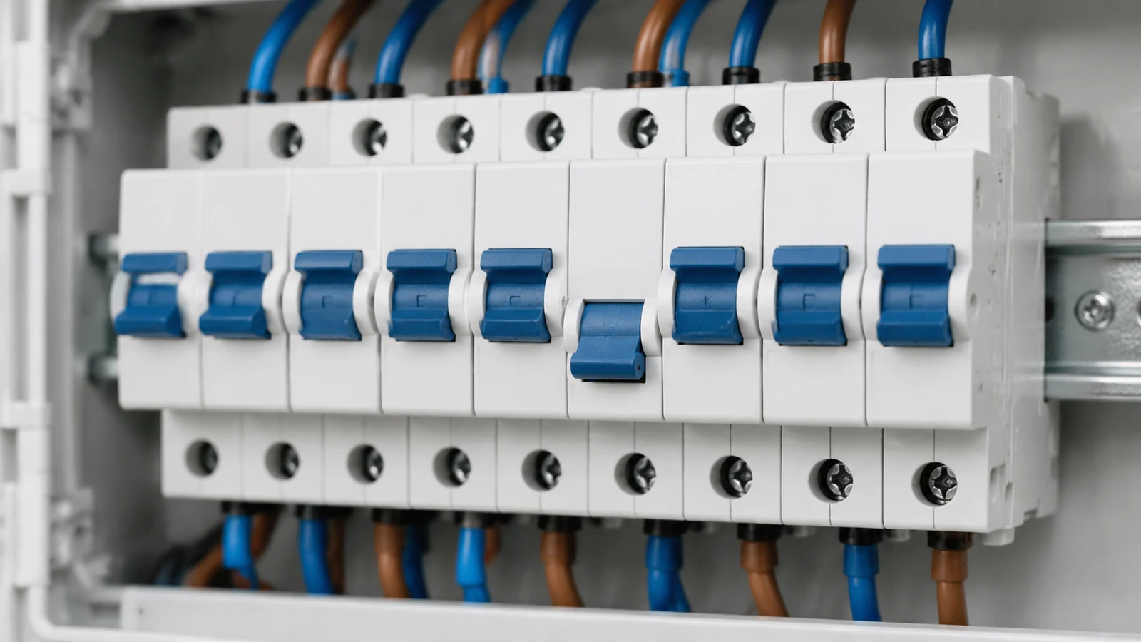
The one thing that is genuinely reduced is the number of devices that can fail. Twelve RCBOs are twelve residual current sensors, each with its own test button and its own periodic test obligation. Twelve devices to test once a quarter is a maintenance load that a shared RCCB does not create — and an untested RCBO is a device whose protection is assumed rather than known.
The table compares the two arrangements for a twelve-way board. Widths and prices are indicative only — they vary by range and by market — but the relationships hold.
| Consideration | 12 MCBs + 2 shared RCCBs | 12 RCBOs |
|---|---|---|
| Modules used | 12 for the MCBs, plus 2 or 4 for the RCCBs depending on pole configuration | 12, and an RCBO is often one module wider than the equivalent MCB |
| Devices to buy | 12 + 2 | 12, but each is a more complex product |
| Cost per way | Lower on the bill of materials | Higher per device, partly offset by removing the RCCB and its enclosure space |
| Effect of one earth fault | Whole group trips; fault found by testing circuits one at a time | One circuit trips; the fault is identified by inspection |
| Accumulated leakage | Adds across all connected loads on the group | Confined to one circuit |
| Maintenance | Two test buttons to operate and record | Twelve test buttons, each with its own record |
| Future extension | Adding a way may require re-balancing the groups | Adding a way is additive — one device, one circuit |
The cost conclusion depends on what the client values. On a specification driven purely by first cost, the split arrangement wins and always will. On any installation where a trip means a callout — a shop, a clinic, a rented flat with a tenant who cannot reset a board over the phone — the per-way arrangement pays for itself the first time it avoids a callout.
The split arrangement is not obsolete, and there are cases where it is the better engineering choice.
The judgement is not “RCBO good, RCD bad”. It is whether the circuits sharing a device have anything in common that justifies sharing the consequences of a trip.
Most RCBO callouts are installation errors rather than device failures, and they cluster around the neutral.
The neutral must pass through the device it belongs to. An RCBO measures line and neutral together. If the circuit’s neutral is taken from a shared neutral bar instead of from the RCBO’s own neutral terminal, the device sees current going out and none coming back, and it trips immediately on load. This is the single most common reason a newly installed RCBO “doesn’t work”.
Shared neutrals break the arrangement entirely. Two circuits sharing one neutral cannot each have their own residual current device, because the return current of one circuit passes through the sensor of the other. Any board being converted from shared-neutral wiring to per-way RCBOs needs the neutrals separated first — which is cable work, not accessory work.
1P+N and 2P are not interchangeable. A 1P+N device switches and protects the line, and switches the neutral. A 2P device protects both poles. Which one is required depends on the earthing system and on the project specification, and the choice changes the terminal arrangement as well as the price. The difference matters most where the supply polarity is not guaranteed.
Test buttons need to be reachable and the result recorded. An RCBO buried behind a fixed cover, or in a board that requires a tool to open, will not be tested. If the maintenance regime assumes quarterly testing, the board layout has to make that realistic.
An RCBO is not a single product. The residual current sensing element comes in types, and the type decides what kind of earth fault it can detect.
Type AC responds to alternating residual current only. It is the traditional choice and it is still widely sold.
Type A responds to alternating residual current and to pulsating direct residual current — the kind produced by electronic equipment with rectifier front ends, which is now most of what is plugged into a modern installation.
Type B and Type F extend the range further, for smooth direct current and for mixed-frequency residual currents respectively, and are specified for particular equipment rather than as a general default.
The practical point for a board builder: the type is part of the specification and it has to be ordered explicitly. A type AC device will not detect a fault current it was never designed to see, and no amount of testing at commissioning reveals the gap — the device simply does not respond. The reasoning behind the types is set out in the residual current protection explanation.
Steps 3 to 5 are where a board ends up non-compliant while every individual device is perfectly good. They are specification decisions, and they cannot be corrected by a fitter at assembly.
Functionally yes — it combines overcurrent protection with residual current protection in one device. Practically, it is a different product with its own standard, its own test procedure, and a residual current type that has to be specified. Treating it as a drop-in replacement for an MCB plus an RCD loses the type and sensitivity decisions.
Only if each circuit already has its own neutral run back to the board. Where circuits share a neutral, per-way residual current devices will trip as soon as either circuit is loaded, because the return current passes through the wrong sensor. The neutrals have to be separated first.
On the bill of materials, usually yes. The comparison has to include the RCCB, its enclosure space, and the cost of the callouts that a shared device generates — which is where the two arrangements often converge over the life of the board.
Almost always a neutral wiring error: the circuit’s neutral is taken from a shared bar rather than from the RCBO’s own neutral terminal, so the device sees current leaving without returning. Check that before suspecting the device.
Yes. The test button verifies that the mechanism operates, and it should be operated and recorded at the interval the installation’s maintenance regime specifies. A device that has never been tested is a device whose protection is assumed.
The question is not which device is better. It is whether the circuits on a shared device have enough in common to share a trip. Where they do — a group of lighting circuits, a sub-board with a handful of similar ways — the split arrangement is sound and cheaper. Where they do not, per-way protection buys fault identification, isolation and immunity to accumulated leakage, and it does so at the cost of a wider board and more test buttons.
Our miniature circuit breaker and RCBO range lists pole configurations and residual current types per family, and how to specify an MCB range covers the ordering data that has to be agreed before a board schedule becomes a purchase order. If you are comparing the two arrangements for a specific board, send us the way list and we will set them side by side in modules and in devices.