MCCB Bakım ve Muayene Programı: Neler Kontrol Edilmeli ve Ne Zaman
Pratik bir MCCB bakım kontrol listesi: aralık nasıl belirlenir, ne ölçülmelidir, devre kesme testi neyi kanıtlayabilir ve sahada asla neyin açılmaması gerekir.
Devamını Oku Turkish

A 690 V MCCB and a 415 V MCCB can look almost identical on the outside. Same frame, same handle, same terminal layout, often the same catalogue page. The difference is inside the arc chamber and in the numbers the manufacturer is willing to put its type test behind — and that difference is what decides whether the breaker clears a fault or becomes part of it.
690 V is not an exotic voltage. In IEC markets it is the next standard step above 400 V: a 400/690 V system carries 690 V between phases and 400 V from phase to neutral, which is why 400 V equipment works from it and why the breakers feeding three-phase loads have to be rated at 690 V. Where that system appears — ships, mines, cement plants, heavy process lines, wind converters — the switchgear is often specified by an overseas client while the panel is built locally from whatever the distributor stocks.
This article covers the four voltage numbers on a breaker datasheet, why a 415 V breaking capacity cannot be reused at 690 V, what insulation coordination actually demands at this level, how pole and neutral arrangements differ, and the checks to make before a 690 V unit goes into a panel.
Four different numbers get confused with each other, and the confusion is expensive. A device can legitimately declare an insulation voltage of 800 V while only being usable at 415 V in service, because insulation voltage and operating voltage answer different questions.
| Declaration | Nedir? | What it governs | What it does not tell you |
|---|---|---|---|
| Ue — rated operational voltage | The voltage at which the declared current and breaking-capacity ratings are valid | Whether the device may be connected to your system at all | Which fault level it can break, unless Icu is tabulated at that same voltage |
| Ui — rated insulation voltage | The design voltage of the insulation system, referenced to clearance and creepage distances | Dielectric verification and insulation coordination headroom | Nothing about continuous operation; a high Ui is not a licence to run at that voltage |
| Uimp — rated impulse withstand voltage | The peak transient the insulation survives without breakdown | Coordination with the overvoltage category of the installation point | Nothing about thermal or switching performance |
| Icu / Ics at a stated Ue | Ultimate and service breaking capacity, verified at one specific voltage | Short-circuit protection at that voltage and no other | What happens one voltage step higher |
The practical rule that follows: 690 V capability is not a property of the device, it is a property of a row in a table. A breaker is a 690 V breaker when its datasheet tabulates Ue = 690 V together with an Icu at 690 V, and when that combination sits inside the scope of its type test certificate. Anything less is a claim, not a rating.
When a breaker interrupts a short circuit, the arc is driven into a stack of steel plates that split it into a series of short arcs. Each short arc contributes a roughly fixed voltage drop at its electrodes, and the sum of those drops has to exceed the recovery voltage that the system applies across the open contacts immediately after current zero. If it does not, the arc restrikes and the interruption fails.
Raise the system voltage from 415 V to 690 V and the recovery voltage rises by two thirds while the arc stack stays the same size. The device has two ways to stay honest: build a longer arc chute with more plates, or accept a lower current at the higher voltage. Most manufacturers do both, which is why the same frame shows a different kA figure for every voltage step.
The numbers are on the nameplate, and they are worth reading once because they end the argument permanently. On the SNSX 400F frame in the kalıplı gövdeli devre kesici serisi, the IEC 60947-2 table reads:
| Ue (V) | Icu (kA) | Ics (kA) |
|---|---|---|
| 220 / 240 | 40 | 40 |
| 380 / 415 | 36 | 36 |
| 440 | 30 | 30 |
| 500 | 25 | 25 |
| 525 | 22 | 22 |
| 660 / 690 | 8 | 8 |
The same device that breaks 36 kA at 415 V breaks 8 kA at 690 V. That is a factor of 4.5, and it is not unusual — a drop to somewhere between half and a quarter of the 415 V figure is normal across the range. Anyone who sizes a 690 V feeder from the 415 V column has effectively assumed four times the fault level the breaker can actually clear.
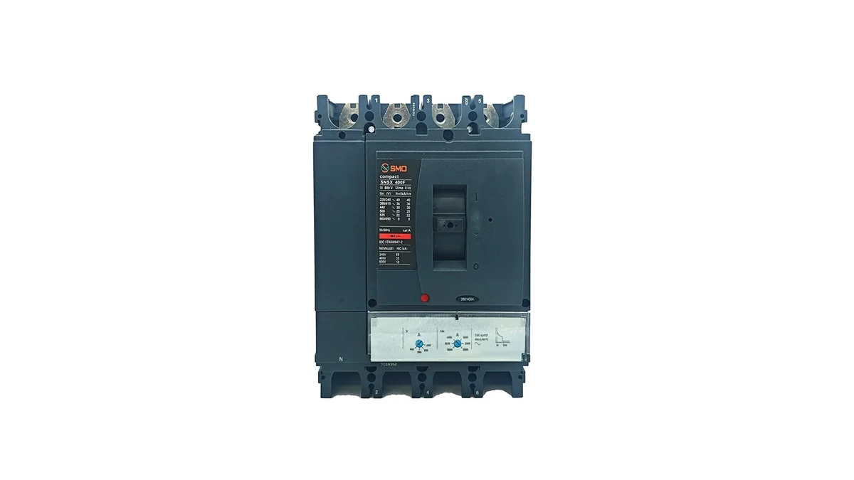
Two details in that table deserve a second look. First, Ics equals Icu at every voltage on this frame, which means the breaker is declared to remain serviceable after clearing its full rated fault current. That is not universal — plenty of devices declare an Ics well below Icu, and after a fault at the Ics limit the device is expected to be replaced rather than reset. Second, the frame is marked category A, so it has no rated short-time withstand current and no intentional short-time delay. Where time-graded selectivity is required at 690 V, a category B device with a declared Icw is the starting point, not an optional upgrade.
Breaking capacity is the number buyers argue about. Insulation is the one that causes fires, and it works on a different basis. IEC 60664-1 derives the required clearances and creepage distances from four inputs: the working voltage, the pollution degree of the environment, the overvoltage category of the installation point, and the tracking resistance of the insulating material.
At 690 V every one of those inputs pushes the distances up. The working voltage across adjacent poles is 690 V rather than 400 V; the clearance in air steps up with it, and the creepage distance along the surface steps up further once pollution degree 3 and a mid-range material group are assumed. This is why a 690 V device is physically bigger than a 415 V device of the same current — the extra volume is mostly air and surface path, not copper.
The impulse side matters just as much. Distribution switchgear sits in overvoltage category III, and the rated impulse withstand voltage the standard requires rises as the nominal system voltage rises. A device that declares 8 kV of Uimp, as the frame above does alongside a Ui of 800 V, carries headroom for the transients that arrive from switching and from the supply side. A device declared at a lower Uimp may be perfectly sound on a 400 V system and inadequate one step up.
Panel builders should also remember that altitude works against all of this. Air thins, dielectric strength falls, and the correction has to be applied on top of an already tighter design — the same principle that drives current derating for temperature and altitude. A 690 V panel bound for a site at 2,000 m cannot be assessed on sea-level data.
In a 400/690 V system the phase-to-phase voltage is 690 V and the phase-to-neutral voltage is 400 V. That single sentence explains most of the pole decisions.
A three-pole device on a 690 V system has 690 V standing across its pole gaps whenever it is open, so it must be a 690 V device in the sense described above — not because of the current it carries, but because of the voltage it has to hold off. This is also the case where a four-pole device earns its cost: where the neutral is distributed, where the neutral has to be switched for isolation, or where the neutral is sized to carry harmonic current.
Three arrangements cover most panels:
Earthing arrangement changes the voltage stress rather than the pole count. In an IT system the first earth fault does not produce a large fault current, so the installation keeps running with one phase sitting at a raised potential to earth, and every pole has to hold off more than it would in a TN system until the fault is located. The device still needs Ue = 690 V; what changes is how much headroom you want above it. The trade-offs between pole configurations are covered in more depth in the three-pole versus four-pole comparison.
690 V is chosen for one of two reasons: the load is large enough that the higher voltage cuts current enough to shrink cables, or the surrounding installation already runs at that level and the panel has to match it.
The first reason dominates in heavy industry. Doubling the voltage halves the current for the same power, and halving the current quarters the resistive losses in a given cable — which is why long feeds to remote motors are cheaper at 690 V than at 400 V even after the switchgear premium. Cement kilns, mine conveyors, steel mill drives and large pump sets all sit in that category.
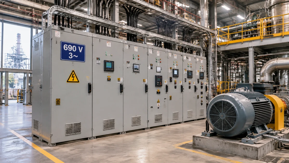
The second reason dominates in marine and offshore work, where 690 V is a long-established shipboard distribution voltage, and in wind generation, where the converter and the generator-side distribution often run at that level. In both cases the specification arrives from the client’s standard and the panel builder’s job is to meet it without renegotiating the design.
One boundary is worth stating plainly: 690 V is an IEC number. North American equipment is rated under UL 489 and NEMA conventions at 600 V, and a 600 V listing does not make a device suitable for a 690 V IEC system even though the numbers look close. Where a project crosses that line, the two rating systems have to be reconciled item by item — the IEC and UL rating systems diverge on exactly this point.
There is a piece of good news buried in the bad news about breaking capacity. For the same transformer, the prospective short-circuit current falls as the system voltage rises.
Take a 1,000 kVA transformer with 6% impedance. On its 400 V side the bolted fault current is about 24.1 kA; on its 690 V side it is about 13.9 kA, because the same kVA is delivered at a higher voltage and the current scales inversely. The arithmetic is the familiar olası kısa devre akımı hesaplaması, and it explains why an 8 kA device at 690 V is not automatically absurd — it is sometimes the correct answer, and sometimes badly short.
The comparison has to be made at the actual installation point, with motor contribution added. Motors on a 690 V board feed a fault for the first few cycles and can add several times their full-load current to the total; a bus with a few large drives can push the prospective current past a marginal breaker in a way that the transformer alone would not suggest.
Selectivity gets harder at 690 V for a structural reason: the current margin between the upstream and downstream breaking capacities narrows, so ratio-based rules lifted from 400 V practice stop holding. Coordination has to come from the manufacturer’s published tables at 690 V. Where those tables do not exist for a particular pairing, the honest answer is that the pair is untested, and time-graded selectivity with a category B upstream device is the alternative route.
Most of the failures in this category are paperwork failures — the device is fine, but nobody confirmed the specific row of the table that the project depends on. The checklist below is short enough to run on every line of a bill of materials.
None of these checks requires a laboratory. All of them require the datasheet rather than the catalogue headline, and most of them can be settled in a single email before the order is placed. The general sequence for narrowing a frame and rating is set out in the MCCB selection walkthrough, which this list assumes as background.
The failure modes at 690 V are consistent enough to be predictable, and they usually appear in the first weeks rather than years later.
The pattern behind all five is the same: a number was read from the wrong column. A nameplate table with six voltage rows is not decoration — it is the device telling you, in the manufacturer’s own words, exactly how much it can do at each one.
No, not unless the datasheet tabulates Ue = 690 V with an Icu at that voltage. A device declared only up to 415 V has not been type tested at 690 V, and the arc chute that clears 36 kA at 415 V is not the same arc chute that clears a fault with 690 V of recovery voltage across the contacts.
No. Ui is the insulation voltage the design is dimensioned for, and it is used for clearance, creepage and dielectric verification. Operating at 690 V requires Ue = 690 V plus a declared breaking capacity at 690 V. The two numbers often appear together on a genuinely 690 V-capable device, which is where the confusion starts.
Because the recovery voltage across the open contacts after current zero is higher, while the arc chute is the same size. The breaker either needs a longer arc stack or must accept less current. The nameplate table is the manufacturer stating which compromise was made — a drop to between half and a quarter of the 415 V figure is common.
The thermal and magnetic thresholds are set by current, not voltage, so the curve type does not change with the system voltage. What does change is the short-circuit level the curve has to coordinate with, so the settings on an adjustable trip unit still have to be checked against the fault study at 690 V.
No. They come from different standards. A 600 V rating belongs to the UL 489 and NEMA framework used in North America, and 690 V belongs to IEC 60947-2. A device listed to 600 V is not thereby rated for a 690 V IEC system, and projects that mix the two have to reconcile the ratings line by line.
690 V capability lives in a table, not in a headline. Confirm Ue at 690 V, read the Icu and Ics that go with it, check Ui and Uimp against the insulation coordination requirement, and make sure the type test certificate actually covers the voltage you are buying for. A device that breaks 36 kA at 415 V and 8 kA at 690 V is a perfectly good breaker — as long as the fault level at the installation point is below 8 kA and everyone involved knows which column was used.
If you are building a 690 V panel and need the rating tables for a specific frame, the MCCB category lists the frames with their per-voltage breaking capacities, and the technical team can confirm the certificate scope for your project voltage before the order is placed.