How to Calculate Prospective Short-Circuit Current and Pick the Right Breaking Capacity
Publicado: Autor: Rachel
Knowing what Icu and Ics mean is one thing. Knowing what fault current your board will actually see is another, and it is the number every breaking capacity decision depends on. Yet it is routinely guessed — usually by copying whatever rating was used on the last job.
Guessing fails in both directions. Underestimate and you install a breaker that cannot safely clear the fault it faces, which is a genuine safety hazard rather than a performance shortfall. Overestimate and you pay a premium across every board in the building for capacity that will never be used. This guide walks through the calculation, the adjustments that matter, and how the result maps onto a breaking capacity rating.
Start With the Transformer
For a single transformer feeding a radial low-voltage system, the transformer impedance dominates everything upstream of it. The HV network is usually large enough that its contribution is small by comparison, so ignoring it gives a slightly conservative answer — which is the right kind of wrong.
The relationship is simple. Transformer impedance is quoted as the percentage of primary voltage needed to drive full-load current into a shorted secondary. A transformer with 5% impedance therefore delivers roughly 100 ÷ 5 = 20 times its full-load current into a bolted fault.
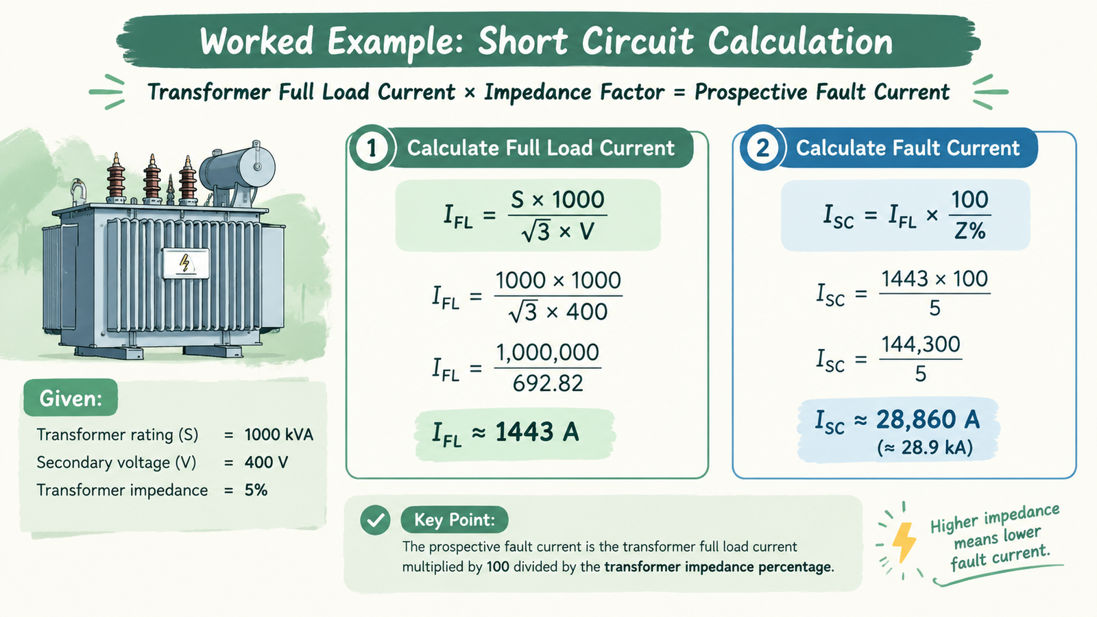
So the two-step method is:
Step 1 — full-load current: I FL = kVA × 1000 ÷ (√3 × V)
Step 2 — fault current: I sc ≈ I FL × 100 ÷ Z%
Worked example: a 1,000 kVA transformer, 400 V secondary, 5% impedance.
I FL = 1,000 × 1000 ÷ (1.732 × 400) = 1,443 A
I sc = 1,443 × 100 ÷ 5 = 28,867 A ≈ 28.9 kA
That single result already matters: a 1,000 kVA transformer with 5% impedance produces close to 29 kA at its terminals. Specifying a 25 kA board immediately downstream of it is one of the more common and more serious specification errors in LV distribution.
Fault Levels Fall as You Move Downstream
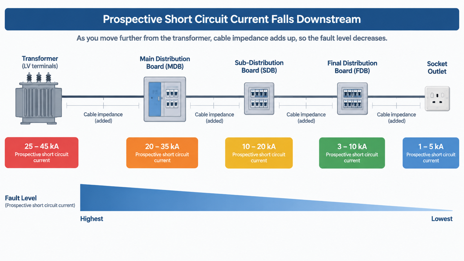
The transformer figure is the ceiling, not the number that applies everywhere. Every metre of cable between the source and the fault adds impedance, and added impedance reduces fault current. A board 30 m from a 630 kVA transformer will see materially less fault current than the transformer terminals do.
Typical ranges in a commercial installation:
Location
Typical prospective fault current
Why
Transformer LV terminals
25–45 kA
Only transformer impedance limits it
Main distribution board
20–35 kA
Short cable run from transformer
Sub-distribution board
10–20 kA
20–50 m of cable adds meaningful impedance
Final distribution board
3–10 kA
Longer runs, smaller conductors
Socket outlet
1–5 kA
End of a long final circuit
This is where the money is. Specifying the same 50 kA rating at every level of a distribution system is a habit, not a calculation. A 50 kA assembly can cost substantially more than a 25 kA one of the same configuration, and across ten sub-distribution boards that difference is real capital expenditure spent on nothing.
When the Simple Method Is Not Enough
The transformer-only formula is a sound first approximation for a single transformer feeding a radial system. It stops being adequate when:
Transformers run in parallel — contributions add at the common bus.
There is significant motor load — running motors feed current back into a fault for the first few cycles, commonly several times their full-load current.
On-site generation is present — generators and battery systems add fault current.
Cable runs are long or unusually sized — impedance must be calculated from conductor data, not estimated.
The supply authority may upgrade the network — today’s fault level is a floor, not a ceiling.
For these cases the standard method is IEC 60909, or the equivalent national method. In practice this means power system software rather than a spreadsheet, because the moment you have parallel sources and unbalanced faults the arithmetic stops being tractable by hand.
Adding Motor Contribution
The transformer is not the only source. Motors that are running when a fault occurs do not simply coast — for the first few cycles they act as generators and feed current back into the fault. On a board with substantial motor load, that contribution is not a rounding error.
A reasonable first approximation is to add roughly four to six times the total full-load current of the motors connected at that point, decaying within a few cycles. It matters most for the peak current and for the first-cycle duty, and it is one of the reasons the simple transformer method is treated as a floor in industrial installations rather than a final answer.
The same logic applies to on-site generation. Generators and battery-backed inverters add to the available fault current, though inverter-based sources are typically current-limited and contribute far less than a rotating machine of similar rating. Where generation is present, the source data has to come from the equipment manufacturer rather than from an assumption.
Peak Current Is a Separate Number
The symmetrical RMS value is what you compare against a breaking capacity. But the first half-cycle of a fault also produces a peak asymmetrical current, and that peak is what mechanically stresses busbars, supports and conductor bracing.
Ipk = κ × √2 × Isc, where κ depends on the X/R ratio of the circuit and is typically around 1.5 to 2.2 for LV systems.
Taking the 28.9 kA example with κ = 1.6 gives a peak of roughly 65 kA. A board whose busbar bracing was sized for the peak associated with a lower symmetrical rating may survive the interrupting duty and still fail mechanically. This is why assembly ratings quote both.
Turning the Number Into a Breaking Capacity
Once you have the prospective fault current at the point of installation, selecting the rating is a comparison — with two rules that matter more than the arithmetic:
Use Ics, not Icu, where continuity matters. Icu is the ultimate breaking capacity — the maximum the breaker can interrupt, after which it need not remain serviceable. Ics is the service breaking capacity, quoted as a percentage of Icu, at which the breaker must still be fully functional afterwards. A device with a high Icu but a low Ics ratio is effectively single-use at high fault levels. Our article on capacidade de frenagem (Icu/Ics) covers these definitions in full.
Do not match the rating to the number exactly. Fault levels change. Networks get reinforced, transformers get replaced, and plant gets extended. Leave headroom rather than specifying a device that sits right on the calculated value.
Then step back to the device class. If the calculated level at a given point exceeds what an MCCB comfortably covers, or if the coordination study requires a declared Icw to hold a time delay, the answer at that position may be an air circuit breaker rather than a large MCCB — the trade-off we set out in MCCB vs ACB.
A Practical Workflow
Read the transformer nameplate: kVA, secondary voltage, impedance %.
Calculate full-load current, then apply the impedance factor for the transformer terminal fault level.
Record your assumptions — infinite primary source, nominal impedance — because they are the basis of every number that follows.
Work downstream, subtracting cable impedance at the main board, sub-distribution boards, and final boards.
Add motor and generator contribution where it is significant.
Compare the available fault current at each point against the equipment rating at that point.
Issue the results as a schedule, so the next person extending the installation is not starting from zero.
Mistakes That Repeat Across Projects
Specifying one rating for the whole installation. Fault level falls with distance; a single rating is either unsafe near the source or wasteful far from it.
Using Icu where Ics is the relevant check. Especially on circuits where continued operation after a fault matters.
Ignoring future network changes. The supply authority may increase the available fault level after you commission.
Forgetting motor contribution. In industrial plant with large motor load this can be a material addition to the first cycles of fault current.
Checking the breaker but not the assembly. The panelboard also has a short-circuit current rating, and the peak current governs busbar bracing.
No documentation. An unrecorded calculation cannot be reviewed, and it will be redone — badly — the next time someone adds a board.
Perguntas frequentes
What is prospective short-circuit current?
It is the maximum current that would flow at a given point in the installation if a zero-impedance (bolted) fault occurred there. It is determined by the source impedance and everything between the source and that point.
How do I calculate it from a transformer nameplate?
Calculate the transformer’s full-load current from its kVA and secondary voltage, then divide by the impedance expressed as a decimal — equivalently, multiply full-load current by 100 ÷ Z%. For a 1,000 kVA, 400 V, 5% transformer that gives about 28.9 kA at the terminals.
Does cable length really change the result?
Yes, sometimes substantially. Cable impedance between the source and the fault reduces the fault current, which is why a sub-distribution board 30 m from the transformer sees far less than the transformer terminals do. Long runs and small conductors reduce it most.
Should I compare my calculated value against Icu or Ics?
Icu tells you the maximum the device can interrupt at all. Ics tells you the level at which it will still be serviceable afterwards. Where the circuit needs to remain operational after clearing a fault, Ics is the more appropriate and more conservative figure to check against.
What about the peak current?
The peak asymmetrical current in the first half cycle is higher than the symmetrical RMS value, typically by a factor of 1.5 to 2.2 depending on the X/R ratio. It governs the mechanical withstand of busbars and supports, so the assembly rating must cover it even when the breaker’s interrupting rating is adequate.
Calculate It Once, Then Write It Down
The fault level study is not an academic exercise — it is the input that decides whether your protection is safe and whether your switchgear budget is spent where it does something. One calculation, done properly and recorded, saves both.
If you are sizing MCCBs and want the ratings checked against your transformer data and cable runs, send us the single-line diagram. Contact our engineering team and we will confirm the breaking capacity you actually need at each level.
<p>Shunt trip, undervoltage release, auxiliary contacts and motor operators compared - what each MCCB accessory actually does, when to specify it, and the checklist to order the right one first time.</p>
<p>Direct-on-line, star-delta and soft starters compared on starting current, torque, mechanical stress and cost - with the four questions that decide it.</p>
<p>What Ir, Isd, Ii and Ig mean, how to set them against the circuit rather than the frame, and how Isd and tsd deliver selective coordination between two MCCBs.</p>